Nissan Frontier D40. Manual - part 932


  Index      Nissan     Nissan Frontier D40 (2010 year) - Service and Repair Manual


Search            


Content   ..  930  931  932  933   ..


Nissan Frontier D40. Manual - part 932


RF-12

< COMPONENT DIAGNOSIS >

SUNROOF SWITCH CIRCUIT

SUNROOF SWITCH CIRCUIT

Description

INFOID:0000000005272929

The BCM supplies power to the integrated CPU of the sunroof motor assembly. The tilt and slide functions of
the sunroof motor assembly is controlled by the sunroof switch. 

Component Function Check

INFOID:0000000005272930

1.

 CHECK SUNROOF MOTOR FUNCTION

Do tilt up/down & slide open/close functions operate normally with sunroof switch?
Is the inspection result normal?

YES

>> Sunroof motor assembly is OK.

NO

>> Refer to 

RF-12, "Diagnosis Procedure"

.

Diagnosis Procedure

INFOID:0000000005272931

Regarding Wiring Diagram information, refer to 

RF-33, "Wiring Diagram"

.

1.

 CHECK SUNROOF SWITCH INPUT SIGNAL 

1.

Turn ignition switch ON.

2.

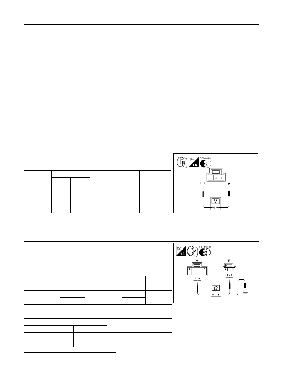
Check voltage between sunroof switch connector and ground.

Are the voltage measurements as specified?

YES

>> Sunroof switch is operating normally. 

NO

>> GO TO 2

2.

 CHECK SUNROOF SWITCH CIRCUITS

1.

Turn ignition switch OFF.

2.

Disconnect sunroof motor assembly connector B83 and sunroof
switch connector R4.

3.

Check continuity between sunroof motor assembly connector
B83 (A) and sunroof switch connector R4 (B) and .

4.

Check continuity between sunroof motor assembly connector B83 (A) and ground. 

Are the continuity test results as specified?

Connector

Terminals

Sunroof switch position

Voltage (V)

(Approx.)

(+)

(–)

R4

1

2

DOWN/OPEN

0V

Other than above

Battery voltage

3

UP/CLOSE

0V

Other than above

Battery voltage

ALKIA1179GB

A

B

Continuity

Connector

Terminal

Connector

Terminal

B83

1

R4

3

Yes

5

1

A

Continuity

Connector

Terminal

B83

5

Ground

No

1

ALKIA1180GB

SUNROOF SWITCH CIRCUIT

RF-13

< COMPONENT DIAGNOSIS >

C

D

E

F

G

H

I

J

L

M

A

B

RF

N

O

P

YES

>> GO TO 3

NO

>> Repair harness or connector.

3.

 CHECK SUNROOF SWITCH

1.

Check continuity between sunroof switch terminals.

Are the continuity test results as specified?

YES

>> Sunroof switch is operating normally.

NO

>> Replace sunroof switch (map lamp assembly). Refer to

INT-24, "Removal and Installation"

.

Terminals

Sunroof switch position

Continuity

1

2

DOWN/OPEN

Yes

Other than above

No

3

UP/CLOSE

Yes

Other than above

No

ALKIA1181GB

RF-14

< COMPONENT DIAGNOSIS >

DOOR SWITCH

DOOR SWITCH

CREW CAB

CREW CAB : Description

INFOID:0000000005272932

Detects door open/close condition.

CREW CAB : Component Function Check

INFOID:0000000005272933

1.

CHECK FUNCTION

With CONSULT-III

Check door switches in data monitor mode with CONSULT-III.

Is the inspection result normal?

YES

>> Door switch is OK.

NO

>> Refer to 

RF-14, "CREW CAB : Diagnosis Procedure"

.

CREW CAB : Diagnosis Procedure

INFOID:0000000005272934

Regarding Wiring Diagram information, refer to 

RF-33, "Wiring Diagram"

.

1.

CHECK DOOR SWITCHES INPUT SIGNAL

With CONSULT-III

Check door switches ("DOOR SW-DR", "DOOR SW-AS", "DOOR SW-RL", "DOOR SW-RR") in DATA MONI-
TOR mode with CONSULT–III. Refer to 

BCS-15, "DOOR LOCK : CONSULT-III Function (BCM - DOOR

LOCK)"

.

• When any doors are open:

• When any doors are closed:

Without CONSULT-III

Check voltage between BCM connector M18 or M19 terminals 12, 13, 47, 48 and ground.

Monitor item

Condition

DOOR SW-DR

CLOSE 

 OPEN: OFF 

 ON

DOOR SW-AS

DOOR SW-RL

DOOR SW-RR

DOOR SW-DR

: ON

DOOR SW-AS

: ON

DOOR SW-RL

: ON

DOOR SW-RR

: ON

DOOR SW-DR

: OFF

DOOR SW-AS

: OFF

DOOR SW-RL

: OFF

DOOR SW-RR

: OFF

DOOR SWITCH

RF-15

< COMPONENT DIAGNOSIS >

C

D

E

F

G

H

I

J

L

M

A

B

RF

N

O

P

Is the inspection result normal?

YES

>> Door switch circuit is OK.

NO

>> GO TO 2

2.

CHECK BCM OUTPUT VOLTAGE

1.

Turn ignition switch OFF.

2.

Disconnect door switches.

3.

Check voltage between BCM connector M18, M19 terminals 12,
13, 47, 48 and ground.

Is the inspection result normal?

YES

>> GO TO 3

NO

>> Replace BCM. Refer to 

BCS-54, "Removal and Installa-

tion"

.

3.

CHECK DOOR SWITCH CIRCUIT

1.

Disconnect door switch and BCM.

2.

Check continuity between door switch connector B8 (Front LH), B108 (Front RH), B18 (Rear LH), B116
(Rear RH) terminal 2 and BCM connector M18, M19 terminals 12, 13, 47 and 48.

3.

Check continuity between door switch connector B8 (Front LH),
B108 (Front RH), B18 (Rear LH), B116 (Rear RH) terminal 2 and
ground.

Is the inspection result normal?

YES

>> GO TO 4

NO

>> Repair or replace harness.

4.

CHECK DOOR SWITCHES

1.

Disconnect door switch.

2.

Check continuity between door switch terminals.

Connec-

tor

Item

Terminals

Condition

Voltage (V)

(Approx.)

(+)

(–)

M19

Front door 

switch LH

47

Ground

Open

Closed

0

Battery voltage

Rear door 

switch LH

48

M18

Front door 

switch RH

12

Rear door 
switch RH

13

LIIA1177E

12 - Ground

: Battery voltage

13 - Ground

: Battery voltage

47 - Ground

: Battery voltage

48 - Ground

: Battery voltage

LIIA1177E

2 - 47

: Continuity should exist.

2 - 12

: Continuity should exist.

2 - 48

: Continuity should exist.

2 - 13

: Continuity should exist.

2 - Ground

: Continuity should not exist.

LIIA1178E


Content   ..  930  931  932  933   ..