Nissan Frontier D40. Manual - part 872


  Index      Nissan     Nissan Frontier D40 (2010 year) - Service and Repair Manual


Search            


Content   ..  870  871  872  873   ..


Nissan Frontier D40. Manual - part 872


MWI

NORMAL OPERATING CONDITION

MWI-93

< SYMPTOM DIAGNOSIS >

C

D

E

F

G

H

I

J

K

L

M

B

A

O

P

NORMAL OPERATING CONDITION

COMPASS

COMPASS : Description

INFOID:0000000005275856

COMPASS

• The electronic compass is highly protected from changes in most magnetic fields. However, some large

changes in magnetic fields can affect it. Some examples are (but not limited to): high tension power lines,
large steel buildings, subways, steel bridges, automatic car washes, large piles of scrap metal, etc. While
this does not happen very often, it is possible.

• During normal operation, the Compass Mirror will continuously update the compass calibration to adjust for

gradual changes in the vehicle's magnetic "remnant" field. If the vehicle is subjected to high magnetic influ-
ences, the compass may appear to indicate false headings, become locked, or appear that it is unable to be
calibrated. If this occurs, perform the calibration procedure.

• If at any time the compass continually displays the incorrect direction or the reading is erratic or locked, ver-

ify the correct zone variance.
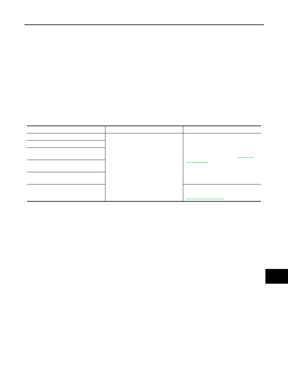
Symptom Chart

Symptom

Cause

Solution / Reference

The compass display reads "C".

• Compass is not calibrated.
• Incorrect zone variance setting.
• Large change in magnetic field (Steel 

bridges, subways, concentrations of 
metal, car washes, etc.)

• Compass was calibrated incorrectly or 

in the presence of a strong magnetic 
field.

Perform Calibration. Refer to 

MWI-21, 

"Description"

.

Compass shows the wrong direction.

Compass does not change direction ap-
pears "Locked".

Compass does not show all the directions, 
one or more is missing.

The compass was calibrated but it "loses" 
calibration.

On long trips the compass shows the 
wrong direction.

Perform Zone Variation Setting if correct 
reading is desired in that location. Refer to 

MWI-21, "Description"

.

MWI-94

< PRECAUTION >

PRECAUTIONS

PRECAUTION

PRECAUTIONS

Precaution for Supplemental Restraint System (SRS) "AIR BAG" and "SEAT BELT 
PRE-TENSIONER"

INFOID:0000000005561529

The Supplemental Restraint System such as “AIR BAG” and “SEAT BELT PRE-TENSIONER”, used along
with a front seat belt, helps to reduce the risk or severity of injury to the driver and front passenger for certain
types of collision. This system includes seat belt switch inputs and dual stage front air bag modules. The SRS
system uses the seat belt switches to determine the front air bag deployment, and may only deploy one front
air bag, depending on the severity of a collision and whether the front occupants are belted or unbelted.
Information necessary to service the system safely is included in the SR and SB section of this Service Man-
ual.

WARNING:

• To avoid rendering the SRS inoperative, which could increase the risk of personal injury or death in

the event of a collision which would result in air bag inflation, all maintenance must be performed by
an authorized NISSAN/INFINITI dealer.

• Improper maintenance, including incorrect removal and installation of the SRS, can lead to personal

injury caused by unintentional activation of the system. For removal of Spiral Cable and Air Bag
Module, see the SR section.

• Do not use electrical test equipment on any circuit related to the SRS unless instructed to in this

Service Manual. SRS wiring harnesses can be identified by yellow and/or orange harnesses or har-
ness connectors.

PRECAUTIONS WHEN USING POWER TOOLS (AIR OR ELECTRIC) AND HAMMERS

WARNING:

• When working near the Airbag Diagnosis Sensor Unit or other Airbag System sensors with the Igni-

tion ON or engine running, DO NOT use air or electric power tools or strike near the sensor(s) with a
hammer. Heavy vibration could activate the sensor(s) and deploy the air bag(s), possibly causing
serious injury.

• When using air or electric power tools or hammers, always switch the Ignition OFF, disconnect the

battery, and wait at least 3 minutes before performing any service.

MWI

COMBINATION METER

MWI-95

< ON-VEHICLE REPAIR >

C

D

E

F

G

H

I

J

K

L

M

B

A

O

P

ON-VEHICLE REPAIR

COMBINATION METER

Removal and Installation

INFOID:0000000005275858

1.

Remove the cluster lid A. Refer to 

IP-11, "Removal and Installation"

2.

Remove the combination meter, using a power tool.

3.

Disconnect the combination meter electrical connectors.

INSTALLATION

Installation is in the reverse order of removal. 

ALJIA0460ZZ

1.

Combination meter

2.

Cluster lid A

3.

Ignition key lamp assembly

4.

 Steering lock escutcheon

Metal clip

PB-1

BRAKES

C

D

E

G

H

I

J

K

L

M

SECTION 

PB

A

B

PB

N

O

P

CONTENTS

PARKING BRAKE SYSTEM

PRECAUTION ...............................................

2

PRECAUTIONS ...................................................

2

Precaution for Supplemental Restraint System 
(SRS) "AIR BAG" and "SEAT BELT PRE-TEN-
SIONER" .................................................................
..

2

PREPARATION ............................................

3

PREPARATION ...................................................

3

Commercial Service Tool  ..........................................

3

ON-VEHICLE REPAIR ..................................

4

PARKING BRAKE SYSTEM ...............................

4

On-Vehicle Service  ...................................................

4

REMOVAL AND INSTALLATION  ................

5

PARKING BRAKE CONTROL ...........................

5

Component ...............................................................

5

Removal and Installation  ..........................................

6

PARKING BRAKE SHOE  ..................................

7

Component ...............................................................

7

Removal and Installation  ..........................................

7

SERVICE DATA AND SPECIFICATIONS 
(SDS) ............................................................

10

SERVICE DATA AND SPECIFICATIONS 
(SDS) .................................................................

10

Parking Drum Brake  ................................................

10

Parking Brake Control  .............................................

10


Content   ..  870  871  872  873   ..