Nissan Frontier D40. Manual - part 816


  Index      Nissan     Nissan Frontier D40 (2010 year) - Service and Repair Manual


Search            


Content   ..  814  815  816  817   ..


Nissan Frontier D40. Manual - part 816


LAN

TROUBLE DIAGNOSIS

LAN-51

< FUNCTION DIAGNOSIS >

[CAN]

C

D

E

F

G

H

I

J

K

L

B

A

O

P

N

TROUBLE DIAGNOSIS

CAN Diagnostic Support Monitor

INFOID:0000000005272388

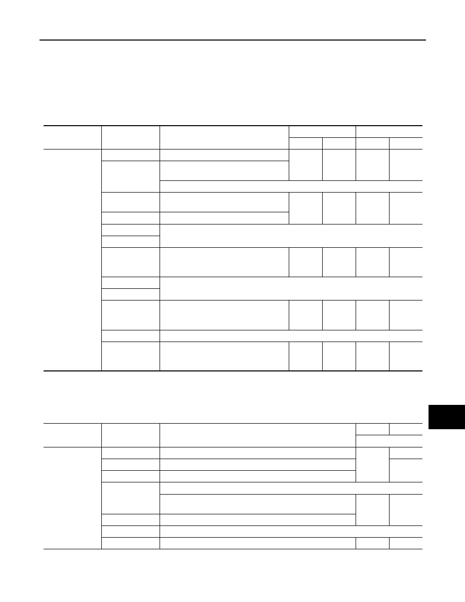
Use “CAN DIAG SUPPORT MNTR” for detecting the root cause.

MONITOR ITEM LIST (CONSULT-III)

ECM

0: Error at present, 1 – 39: Error in the past (Number means the number of times the ignition switch is turned OFF

ON)

*: 39 or higher number is fixed at 39 until the self-diagnosis result is erased.

TCM

NOTE:
Replace the unit when “NG” is indicated on the “INITIAL DIAG”.

Transfer Control Unit

NOTE:
Replace the unit when “NG” is indicated on the “INITIAL DIAG”.

ITEM

CAN DIAG SUP-

PORT MNTR

Description

Normal

Error

PRSNT

PAST

PRSNT

PAST

ECM

TRANSMIT DIAG

Signal transmission status

OK

OK

or

1 – 39

*

UNKWN

0

VDC/TCS/ABS

With VDC: Signal receiving status from the 
ABS actuator and electric unit (control unit)

With ABS: Not used even though indicated

METER/M&A

Signal receiving status from the combina-
tion meter

OK

OK

or

1 – 39

*

UNKWN

0

BCM/SEC

Signal receiving status from the BCM

ICC

Not used even though indicated

HVAC

TCM

Signal receiving status from the TCM

OK

OK

or

1 – 39

*

UNKWN

0

MULTI AV

Not used even though indicated

EPS

IPDM E/R

Signal receiving status from the IPDM E/R

OK

OK

or

1 – 39

*

UNKWN

0

e4WD

Not used even though indicated

AWD/4WD

Signal receiving status from the transfer 
control unit

OK

OK

or

1 – 39

*

UNKWN

0

ITEM

CAN DIAG SUP-

PORT MNTR

Description

Normal

Error

PRSNT

TCM

INITIAL DIAG

Status of CAN controller

OK

NG

TRANSMIT DIAG

Signal transmission status

UNKWN

ECM

Signal receiving status from the ECM

VDC/TCS/ABS

With ABS: Not used even though indicated

With VDC: Signal receiving status from the ABS actuator and elec-
tric unit (control unit)

OK

UNKWN

METER/M&A

Signal receiving status from the combination meter

ICC/e4WD

Not used even though indicated

AWD/4WD

Signal receiving status from the transfer control unit

OK

UNKWN

LAN-52

< FUNCTION DIAGNOSIS >

[CAN]

TROUBLE DIAGNOSIS

BCM

NOTE:
Replace the unit when “NG” is indicated on the “INITIAL DIAG”.

Differential Lock Control Unit

NOTE:
Replace the unit when “NG” is indicated on the “INITIAL DIAG”.

Combination Meter

ITEM

CAN DIAG SUP-

PORT MNTR

Description

Normal

Error

PRSNT

4WD

INITIAL DIAG

Status of CAN controller

OK

NG

TRANSMIT DIAG

Signal transmission status

UNKWN

ECM

Signal receiving status from the ECM

VDC/TCS/ABS

Signal receiving status from the ABS actuator and electric unit (con-
trol unit)

TCM

Signal receiving status from the TCM

METER/M&A

Signal receiving status from the combination meter

ITEM

CAN DIAG SUP-

PORT MNTR

Description

Normal

Error

PRSNT

BCM

INITIAL DIAG

Status of CAN controller

OK

NG

TRANSMIT DIAG

Signal transmission status

UNKWN

ECM

Signal receiving status from the ECM

IPDM E/R

Signal receiving status from the IPDM E/R

METER/M&A

Signal receiving status from the combination meter

I-KEY

Not used even though indicated

ITEM

CAN DIAG SUP-

PORT MNTR

Description

Normal

Error

PRSNT

DIFF

INITIAL DIAG

Status of CAN controller

OK

NG

TRANSMIT DIAG

Signal transmission status

UNKWN

ECM

Signal receiving status from the ECM

VDC/TCS/ABS

Signal receiving status from the ABS actuator and electric unit (con-
trol unit)

AWD/4WD

Signal receiving status from the transfer control unit

LAN

TROUBLE DIAGNOSIS

LAN-53

< FUNCTION DIAGNOSIS >

[CAN]

C

D

E

F

G

H

I

J

K

L

B

A

O

P

N

0: Error at present, 1 – 39: Error in the past (Number means the number of times the ignition switch is turned OFF

ON)

*: 39 or higher number is fixed at 39 until the self-diagnosis result is erased.

ABS Actuator and Electric Unit (Control Unit) (Models with ABS)

CAUTION:

Never replace the unit even when “NG” is indicated on the “INITIAL DIAG” at this stage. Follow the trouble diagnosis proce-
dures. 

ABS Actuator and Electric Unit (Control Unit) (Models with VDC)

CAUTION:

Never replace the unit even when “NG” is indicated on the “INITIAL DIAG” at this stage. Follow the trouble diagnosis proce-
dures. 

IPDM E/R

ITEM

CAN DIAG SUP-

PORT MNTR

Description

Normal

Error

PRSNT

PAST

PRSNT

PAST

M&A

TRANSMIT DIAG

Signal transmission status

OK

OK

or

1 – 39

*

UNKWN

0

ECM

Signal receiving status from the ECM

TCM

Signal receiving status from the TCM

BCM/SEC

Signal receiving status from the BCM

VDC/TCS/ABS

Signal receiving status from the ABS actua-
tor and electric unit (control unit)

IPDM E/R

Signal receiving status from the IPDM E/R

DISPLAY

Not used even though indicated

I-KEY

EPS

AWD/4WD

e4WD

ICC

LANE CAMERA

TIRE-P

ITEM

CAN DIAG SUP-

PORT MNTR

Description

Normal

Error

PRSNT

ABS

INITIAL DIAG

Status of CAN controller

OK

NG

Caution

TRANSMIT DIAG

Signal transmission status

UNKWN

ECM

Signal receiving status from the ECM

ITEM

CAN DIAG SUP-

PORT MNTR

Description

Normal

Error

PRSNT

ABS

INITIAL DIAG

Status of CAN controller

OK

NG

Caution

TRANSMIT DIAG

Signal transmission status

UNKWN

ECM

Signal receiving status from the ECM

TCM

Signal receiving status from the TCM

METER/M&A

Not used even though indicated

STRG

Signal receiving status from the steering angle sensor

OK

UNKWN

ICC

Not used even though indicated

AWD/4WD

Signal receiving status from the transfer control unit

OK

UNKWN

DIFF LOCK

Signal receiving status from the differential lock control unit

LAN-54

< FUNCTION DIAGNOSIS >

[CAN]

TROUBLE DIAGNOSIS

0: Error at present, 1 – 39: Error in the past (Number means the number of times the ignition switch is turned OFF

ON)

*: 39 or higher number is fixed at 39 until the self-diagnosis result is erased.

DTC Index

INFOID:0000000005272389

ITEM

CAN DIAG SUP-

PORT MNTR

Description

Normal

Error

PRSNT

PAST

PRSNT

PAST

IPDM-E

TRANSMIT DIAG

Signal transmission status

OK

OK

or

1 – 39

*

UNKWN

0

ECM

Signal receiving status from the ECM

BCM/SEC

Signal receiving status from the BCM

DTC

Self-diagnosis item

 (CONSULT-III indication)

DTC detection condition

Inspection/Action

U0101

LOST COMM (TCM)

When ECM is not transmitting or receiving CAN commu-
nication signal of OBD (emission-related diagnosis) from 
TCM for 2 seconds or more.

Refer to 

LAN-36

.

U0140

LOST COMM (BCM)

When ECM is not transmitting or receiving CAN commu-
nication signal of OBD (emission-related diagnosis) from 
BCM for 2 seconds or more.

U0164

LOST COMM (HVAC)

When ECM is not transmitting or receiving CAN commu-
nication signal of OBD (emission-related diagnosis) from 
A/C auto amp. or unified meter and A/C amp. for 2 sec-
onds or more.

U1000

CAN COMM CIRCUIT

ECM

When ECM is not transmitting or receiving 
CAN communication signal of OBD (emission-
related diagnosis) for 2 seconds or more.

Except 
for ECM

When a control unit (except for ECM) is not 
transmitting or receiving CAN communication 
signal for 2 seconds or more.

U1001

CAN COMM CIRCUIT

When ECM is not transmitting or receiving CAN commu-
nication signal other than OBD (emission-related diagno-
sis) for 2 seconds or more.

U1002

SYSTEM COMM

When a control unit is not transmitting or receiving CAN 
communication signal for 2 seconds or less.

Start the inspection. Refer 
to the applicable section 
of the indicated control 
unit.

U1010

CONTROL UNIT(CAN)

When an error is detected during the initial diagnosis for 
CAN controller of each control unit.

Replace the control unit 
indicating “U1010” or 
“P0607”.

P0607

ECM


Content   ..  814  815  816  817   ..