Nissan Frontier D40. Manual - part 781
DIAGNOSIS SYSTEM (BCM)
INL-79
< FUNCTION DIAGNOSIS >
[WITHOUT POWER DOOR LOCKS]
C
D
E
F
G
H
I
J
K
M
A
B
INL
N
O
P
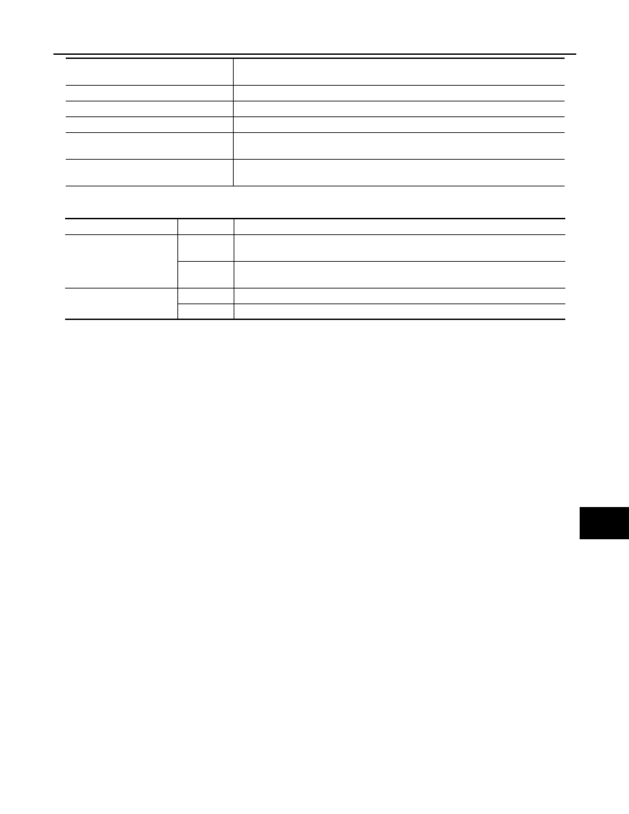
ACTIVE TEST
KEY CYL UN-SW [ON/OFF]
Lock switch status input from door lock and unlock switch
CDL LOCK SW [ON/OFF]
Lock switch status input from door lock and unlock switch
CDL UNLOCK SW [ON/OFF]
Unlock switch status input from door lock and unlock switch
KEYLESS LOCK [ON/OFF]
Lock signal status received from remote keyless entry receiver (integrated in the
BCM)
KEYLESS UNLOCK [ON/OFF]
Unlock signal status received from remote keyless entry receiver (integrated in the
BCM)
Monitor Item
[Unit]
Description
Test Item
Operation
Description
IGN ILLUM
ON
Outputs the ignition keyhole illumination control signal to turn the ignition keyhole il-
lumination lamp ON.
OFF
Stops the ignition keyhole illumination control signal to turn the ignition keyhole illu-
mination lamp OFF.
INT LAMP
ON
Outputs the interior room lamp control signal to turn the interior room lamps ON.
OFF
Stops the interior room lamp control signal to turn the interior room lamps OFF.