Nissan Frontier D40. Manual - part 767
CARGO LAMP CONTROL CIRCUIT
INL-23
< COMPONENT DIAGNOSIS >
[WITH POWER DOOR LOCKS]
C
D
E
F
G
H
I
J
K
M
A
B
INL
N
O
P
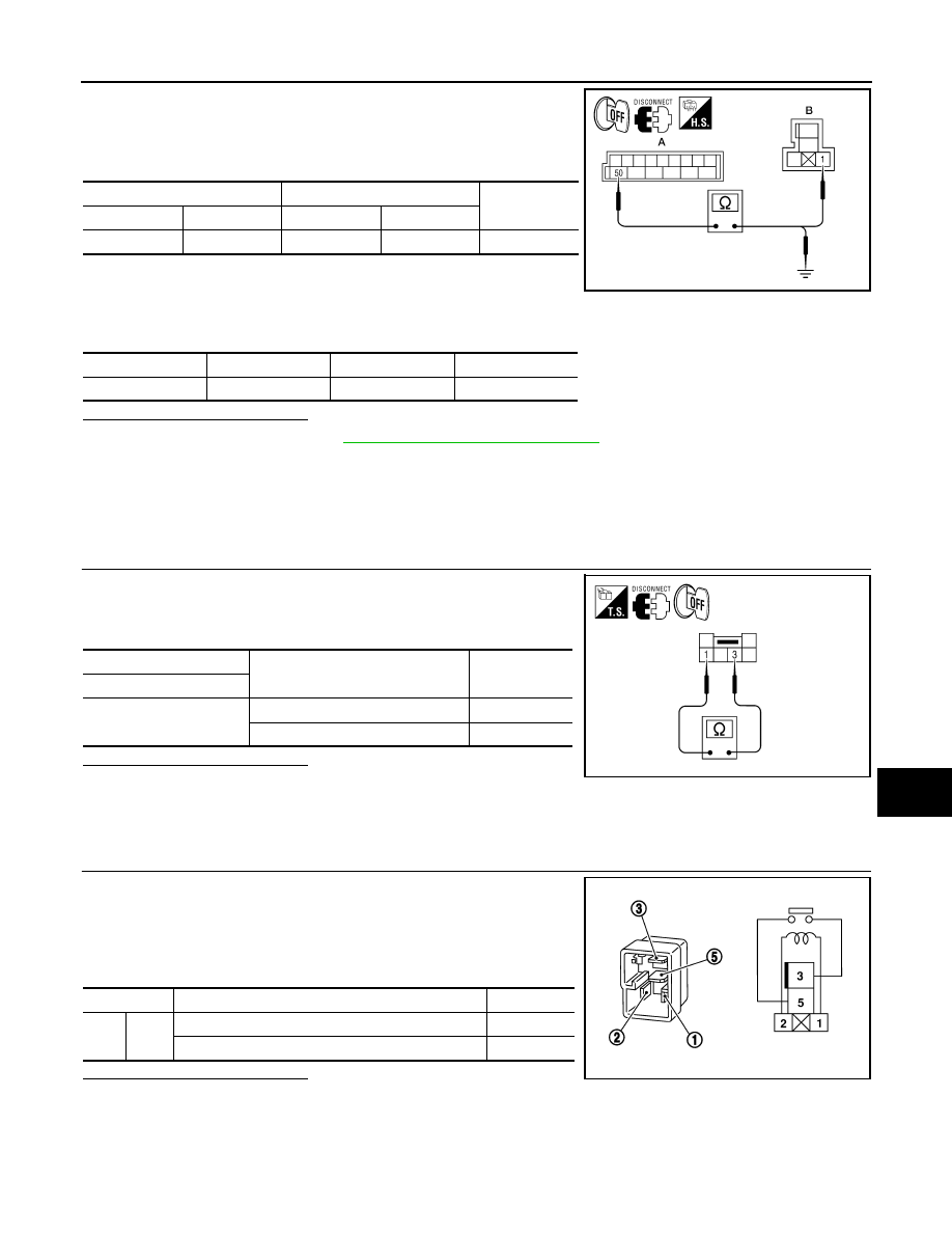
1.
Disconnect BCM connector M19 and cargo lamp relay connec-
tor.
2.
Check continuity between BCM connector M19 (A) terminal 50
and cargo lamp relay connector M165 (B) terminal 1.
3.
Check continuity between BCM connector M19 terminal 50 and ground.
Is the inspection result normal?
YES
>> Replace BCM. Refer to
BCS-54, "Removal and Installation"
NO
>> Repair harness or connectors.
Component Inspection
INFOID:0000000005272819
CARGO LAMP SWITCH
1.
CHECK CARGO LAMP SWITCH
1.
Turn ignition switch OFF.
2.
Disconnect cargo lamp switch connector.
3.
Check continuity between cargo lamp switch terminals.
Is the inspection result normal?
YES
>> Inspection End
NO
>> Replace cargo lamp switch.
CARGO LAMP RELAY
1.
CHECK CARGO LAMP RELAY
1.
Turn ignition switch OFF.
2.
Disconnect cargo lamp relay connector.
3.
Supply power to terminal 2 and ground to terminal 1 of the cargo
lamp relay.
4.
Check continuity between cargo lamp relay terminals 3 and 5.
Is the inspection result normal?
YES
>> Inspection End
NO
>> Replace cargo lamp relay.
BCM
Cargo lamp relay
Continuity
Connector
Terminal
Connector
Terminal
M19 (A)
50
M165 (B)
1
Yes
ALLIA0557GB
Connector
Terminal
—
Continuity
M19 (A)
50
Ground
No
Cargo lamp switch
Condition
Continuity
Terminal
1
−
3
ON
Yes
OFF
No
AWLIA0804ZZ
Terminal
Condition
Continuity
3
5
Power and ground supplied to terminals 1 and 2
Yes
No power and ground supplied
No
SEF497Y