Nissan Frontier D40. Manual - part 762
DIAGNOSIS AND REPAIR WORKFLOW
INL-3
< BASIC INSPECTION >
[WITH POWER DOOR LOCKS]
C
D
E
F
G
H
I
J
K
M
A
B
INL
N
O
P
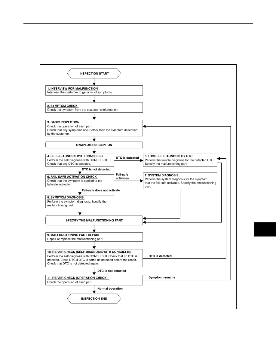
BASIC INSPECTION
DIAGNOSIS AND REPAIR WORKFLOW
Work Flow
INFOID:0000000005272798
OVERALL SEQUENCE
AWLIA1661GB