Nissan Frontier D40. Manual - part 751


  Index      Nissan     Nissan Frontier D40 (2010 year) - Service and Repair Manual


Search            


Content   ..  749  750  751  752   ..


Nissan Frontier D40. Manual - part 751


MAGNET CLUTCH

HAC-107

< COMPONENT DIAGNOSIS >

[MANUAL A/C (TYPE 2)]

C

D

E

F

G

H

J

K

L

M

A

B

HAC

N

O

P

1.

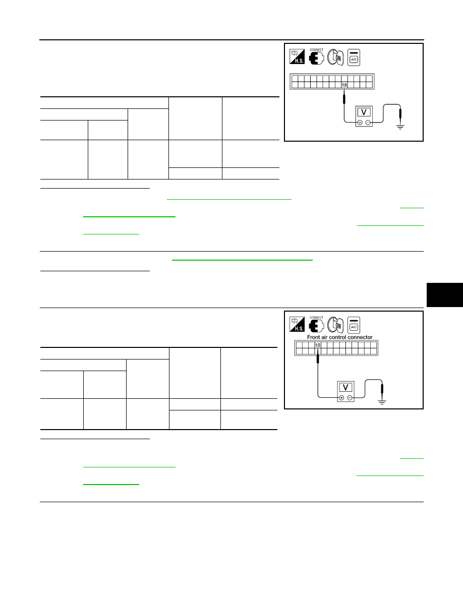
Reconnect BCM connector and front air control connector.

2.

Turn ignition switch ON.

3.

Turn A/C switch ON.

4.

Check voltage between front air control harness connector M49
terminal 18 and ground.

Is the inspection result normal?

YES

>> Replace BCM. Refer to 

BCS-54, "Removal and Installation"

.

NO-1

>> If the voltage is approx. 5V when blower motor is ON, replace front air control. Refer to 

VTL-7,

"Removal and Installation"

.

NO-2

>> If the voltage is approx. 0V when blower motor is OFF, replace BCM. Refer to 

BCS-54, "Removal

and Installation"

.

7.

CHECK CAN COMMUNICATION

Check CAN communication. Refer to 

LAN-14, "Trouble Diagnosis Flow Chart"

.

Is the inspection result normal?

YES

>> Inspection End.

NO

>> Repair or replace malfunctioning part(s).

8.

CHECK VOLTAGE FOR FRONT AIR CONTROL (A/C COMPRESSOR ON SIGNAL)

1.

Turn ignition switch ON.

2.

Check voltage between front air control harness connector M49
terminal 10 and ground.

Is the inspection result normal?

YES

>> GO TO 9.

NO-1

>> If the voltage is approx. 5V when A/C switch is ON, replace front air control. Refer to 

VTL-7,

"Removal and Installation"

.

NO-2

>> If the voltage is approx. 0V when A/C switch is OFF, replace BCM. Refer to 

BCS-54, "Removal

and Installation"

.

9.

CHECK CIRCUIT CONTINUITY BETWEEN BCM AND FRONT AIR CONTROL

Terminals

Condition

Voltage

(Approx.)

(+)

(-)

Front air con-

trol connector

Terminal 

No.

M49

18

Ground

A/C switch: ON
Blower motor 
operates

0V

A/C switch: OFF

Battery voltage

WJIA1628E

Terminals

Condition

Voltage

(Approx.)

(+)

(-)

Front air 

control con-

nector

Terminal No.

M49

10

Ground

A/C switch: ON

0V

A/C switch: 

OFF

Battery voltage

WJIA1137E

HAC-108

< COMPONENT DIAGNOSIS >

[MANUAL A/C (TYPE 2)]

MAGNET CLUTCH

1.

Turn ignition switch OFF.

2.

Disconnect BCM connector and front air control connector.

3.

Check continuity between BCM harness connector M18 terminal
27 and front air control harness connector M49 terminal 10.

Is the inspection result normal?

YES

>> GO TO 10.

NO

>> Repair harness or connector.

10.

CHECK INTAKE SENSOR CIRCUITS

Check intake sensor. Refer to 

HAC-110, "Intake Sensor Component Inspection"

.

Is the inspection result normal?

YES

>> GO TO 11.

NO

>> Replace intake sensor. Refer to 

VTL-8, "Removal and Installation"

.

11.

CHECK CAN COMMUNICATION

Check CAN communication. Refer to 

LAN-14, "Trouble Diagnosis Flow Chart"

.

Is the inspection result normal?

YES

>> Replace BCM. Refer to 

BCS-54, "Removal and Installation"

.

NO

>> Repair or replace malfunctioning part(s).

12.

CHECK MAGNET CLUTCH CIRCUIT

1.

Turn ignition switch OFF.

2.

Disconnect A/C compressor connector.

3.

Check for operation sound when applying battery voltage to A/C
compressor terminal 1.

Is the inspection result normal?

YES

>> GO TO 13.

NO

>> Replace magnet clutch. Refer to 

HA-30, "Removal and

Installation for Compressor Clutch"

.

13.

CHECK CIRCUIT CONTINUITY BETWEEN IPDM E/R AND A/C COMPRESSOR

1.

Disconnect IPDM E/R connector.

2.

Check continuity between IPDM E/R harness connector E119
terminal 11 and A/C compressor harness connector F3 terminal
1.

Is the inspection result normal?

YES

>> Replace IPDM E/R. Refer to 

PCS-33, "Removal and

Installation of IPDM E/R"

.

NO

>> Repair harness or connector.

27 - 10

: Continuity should exist.

WJIA1136E

WJIA1472E

11 – 1

: Continuity should exist.

WJIA1470E

INTAKE SENSOR

HAC-109

< COMPONENT DIAGNOSIS >

[MANUAL A/C (TYPE 2)]

C

D

E

F

G

H

J

K

L

M

A

B

HAC

N

O

P

INTAKE SENSOR

System Description

INFOID:0000000005275941

COMPONENT DESCRIPTION

Intake Sensor

The intake sensor is located on top of the heater and cooling unit
assembly next to the A/C evaporator cover. It converts temperature
of air after it passes through the evaporator into a resistance value
which is then input to the front air control.

Intake Sensor Diagnosis Procedure

INFOID:0000000005275942

Regarding Wiring Diagram information, refer to 

HAC-117, "Wiring Diagram - Air Conditioner Control - Without

VBC"

.

DIAGNOSTIC PROCEDURE FOR INTAKE SENSOR

SYMPTOM: Intake sensor circuit is open or shorted. 

1.

CHECK VOLTAGE BETWEEN INTAKE SENSOR AND GROUND

1.

Disconnect intake sensor connector.

2.

Turn ignition switch ON.

3.

Check voltage between intake sensor harness connector M146
terminal 2 and ground.

Is the inspection result normal?

YES

>> GO TO 2.

NO

>> GO TO 4.

2.

CHECK CIRCUIT CONTINUITY BETWEEN INTAKE SENSOR AND FRONT AIR CONTROL

WJIA1155E

WJIA1156E

2 - Ground

: Approx. 5V

WJIA1278E

HAC-110

< COMPONENT DIAGNOSIS >

[MANUAL A/C (TYPE 2)]

INTAKE SENSOR

1.

Turn ignition switch OFF.

2.

Disconnect front air control connector.

3.

Check continuity between intake sensor harness connector
M146 terminal 1 and front air control harness connector M49 ter-
minal 13.

Is the inspection result normal?

YES

>> GO TO 3.

NO

>> Repair harness or connector.

3.

CHECK INTAKE SENSOR

Refer to 

HAC-110, "Intake Sensor Component Inspection"

.

Is the inspection result normal?

YES

>> Replace front air control. Refer to 

VTL-7, "Removal and Installation"

.

NO

>> Replace intake sensor. Refer to 

VTL-8, "Removal and Installation"

.

4.

CHECK CIRCUIT CONTINUITY BETWEEN INTAKE SENSOR AND FRONT AIR CONTROL

1.

Turn ignition switch OFF.

2.

Disconnect front air control connector.

3.

Check continuity between intake sensor harness connector
M146 terminal 2 and front air control harness connector M49 ter-
minal 12.

4.

Check continuity between intake sensor harness connector
M146 terminal 2 and ground.

Is the inspection result normal?

YES

>> Replace front air control. Refer to 

VTL-7, "Removal and Installation"

.

NO

>> Repair harness or connector.

Intake Sensor Component Inspection

INFOID:0000000005275943

COMPONENT INSPECTION

Intake Sensor

1 - 13

: Continuity should exist.

WJIA1157E

2 - 12

: Continuity should exist.

2 - Ground

: Continuity should not exist.

WJIA1158E


Content   ..  749  750  751  752   ..