Nissan Frontier D40. Manual - part 720
ELECTRICAL LEAK DETECTOR
HA-23
< ON-VEHICLE MAINTENANCE >
C
D
E
F
G
H
J
K
L
M
A
B
HA
N
O
P
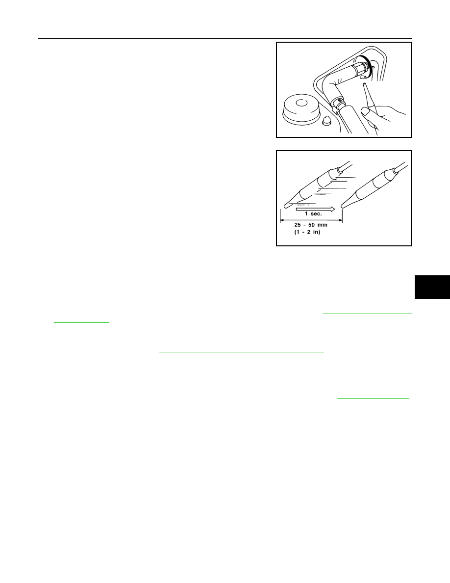
2.
When checking for leaks, circle each fitting completely with the
probe as shown.
3.
Move the probe along each component at a speed of approxi-
mately 25 - 50 mm (1 - 2 in)/second as shown.
CHECKING PROCEDURE
NOTE:
To prevent inaccurate or false readings, make sure there is no refrigerant vapor, shop chemicals, or cigarette
smoke in the vicinity of the vehicle. Perform the leak test in a calm area (low air/wind movement) so that the
leaking refrigerant is not dispersed.
1.
Turn the engine OFF.
2.
Connect the manifold gauge set (J-39183-C) to the A/C service ports. Refer to
3.
Check if the A/C refrigerant pressure is at least 345 kPa (3.52 kg/cm
2
, 50 psi) above a temperature of
16
°
C (61
°
F). If less than specification, recover/evacuate and recharge the system with the specified
amount of refrigerant. Refer to
HA-16, "HFC-134a (R-134a) Service Procedure"
.
NOTE:
At temperatures below 16
°
C (61
°
F), leaks may not be detected since the system may not reach 345 kPa
(3.52 kg/cm
2
, 50 psi) pressure.
4.
Perform the leak test from the high-pressure side (A/C compressor discharge “a” to evaporator inlet “f”) to
the low-pressure side (A/C evaporator drain hose “g” to shaft seal “k”). Refer to
.
Clean the component to be checked and carefully move the electronic refrigerant leak detector probe
completely around the following connections and components.
• Check the compressor shaft seal
• Check the high and low-pressure pipe and hose fittings, relief valve, and compressor shaft seal
• Check the liquid tank
• Check the refrigerant pressure sensor
• Check all around the service valves. Check that the service valve caps are screwed tightly on the ser-
vice valves (to prevent leaks).
NOTE:
After removing manifold gauge set (J-39183-C) from the service valves, wipe any residue from the ser-
vice valves to prevent any false readings by the electronic refrigerant leak detector (J-41995).
• Evaporator
With engine OFF, turn blower fan on “High” for at least 15 seconds to dissipate any refrigerant trace in
the heater and cooling unit assembly. Wait a minimum of 10 minutes accumulation time (refer to the
manufacturer's recommended procedure for actual wait time) before inserting the electronic refrigerant
leak detector probe into the heater and cooling unit assembly drain hose.
NOTE:
Keep the probe inserted for at least 10 seconds. Use caution not to contaminate the probe tip with water
or dirt that may be in the drain hose.
SHA706E
SHA708EA