Nissan Frontier D40. Manual - part 638
COMBINATION SWITCH READING SYSTEM
EXL-25
< FUNCTION DIAGNOSIS >
C
D
E
F
G
H
I
J
K
M
A
B
EXL
N
O
P
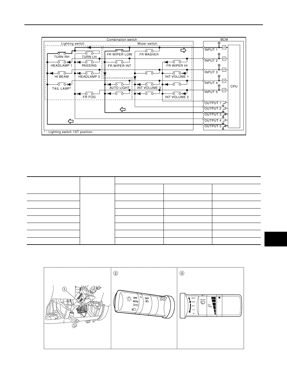
• The circuits between INPUT 1 and OUTPUT 5 and between INPUT 1 and OUTPUT 3 are formed when the
TURN RH switch and FR WIPER LOW switch are turned ON.
• BCM detects the combination switch status signal “1CE” when the signals of OUTPUT 3 and OUTPUT 5 are
input to INPUT 1.
• BCM judges that the TURN RH switch and FR WIPER LOW switch are ON when the signal “1CE” is
detected.
WIPER INTERMITTENT DIAL POSITION SETTING (FRONT WIPER INTERMITTENT OPERATION)
BCM judges the wiper intermittent dial 1 - 7 by the status of INT VOLUME 1, 2 and 3 switches.
Component Parts Location
INFOID:0000000005561513
JPMIA0074GB
Wiper intermittent
dial position
Intermittent
operation delay
interval
INT VOLUME switch ON/OFF status
INT VOLUME 1 switch
INT VOLUME 2 switch
INT VOLUME 3 switch
1
Short
↑
↓
Long
ON
ON
ON
2
ON
ON
OFF
3
ON
OFF
OFF
4
OFF
OFF
OFF
5
OFF
OFF
ON
6
OFF
ON
ON
7
OFF
ON
OFF
ALMIA0416ZZ