Nissan Frontier D40. Manual - part 591


  Index      Nissan     Nissan Frontier D40 (2010 year) - Service and Repair Manual


Search            


Content   ..  589  590  591  592   ..


Nissan Frontier D40. Manual - part 591


EM-96

< DISASSEMBLY AND ASSEMBLY >

[QR25DE]

ENGINE UNIT

CAUTION:

Do not rotate crankshaft.

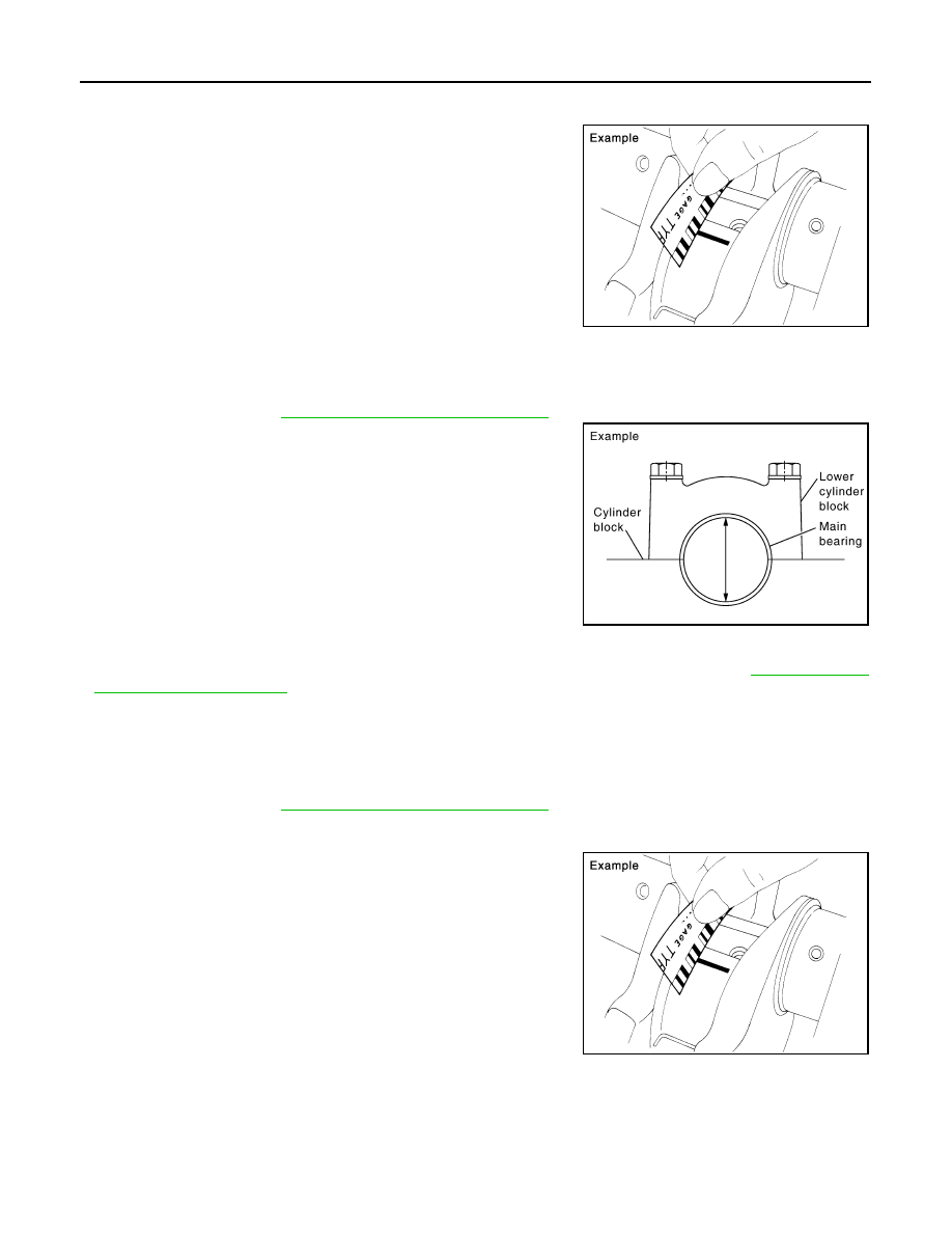
• Remove connecting rod cap and bearing, and using the scale on

the plastigage bag, measure the plastigage width. 
NOTE:
The procedure when the measured value exceeds the limit is
same as that described in the “Method by Calculation”.

MAIN BEARING OIL CLEARANCE

Method by Calculation

• Install main bearings to cylinder block and lower cylinder block, and tighten lower cylinder block bolts to the

specified torque. Refer to 

EM-79, "Disassembly and Assembly"

 for the tightening procedure. 

• Measure the inner diameter of main bearing with a bore gauge.
(Bearing oil clearance) = (Main bearing inner diameter) – (Crank-
shaft main journal diameter)

• If the clearance exceeds the limit, select proper main bearing according to main bearing inner diameter and

crankshaft main journal diameter to obtain the specified bearing oil clearance. Refer to 

EM-99, "How to

Select Piston and Bearing"

.

Method of Using Plastigage

• Remove engine oil and dust on crankshaft main journal and the surfaces of each bearing completely. 
• Cut a plastigage slightly shorter than the bearing width, and place it in crankshaft axial direction, avoiding oil

holes.

• Install main bearings to cylinder block and lower cylinder block, and tighten lower cylinder block bolts to the

specified torque. Refer to 

EM-79, "Disassembly and Assembly"

 for the tightening procedure. 

CAUTION:

Do not rotate crankshaft.

• Remove lower cylinder block and bearings, and using the scale on

the plastigage bag, measure the plastigage width. 
NOTE:
The procedure when the measured value exceeds the limit is
same as that described in the “Method by Calculation”.

MAIN BEARING CRUSH HEIGHT 

PBIC1149E

Standard:

No. 1, 3 and 5 journals

: 0.028 - 0.042 mm (0.0011 - 0.0017 in)

No. 2 and 4 journals

: 0.041 - 0.056 mm (0.0016 - 0.0022 in)

Limit

: 0.1 mm (0.004 in)

PBIC2204E

PBIC1149E

ENGINE UNIT

EM-97

< DISASSEMBLY AND ASSEMBLY >

[QR25DE]

C

D

E

F

G

H

I

J

K

L

M

A

EM

N

P

O

• When lower cylinder block is removed after being tightened to the

specified torque with main bearings installed, the tip end of bearing
must protrude. Refer to 

EM-79, "Disassembly and Assembly"

 for

the tightening procedure.

• If the standard is not met, replace main bearings.

CONNECTING ROD BEARING CRUSH HEIGHT

• When connecting rod bearing cap is removed after being tightened

to the specified torque with connecting rod bearings installed, the
tip end of bearing must protrude. Refer to 

EM-79, "Disassembly

and Assembly"

   for the tightening procedure.

• If the standard is not met, replace connecting rod bearings.

LOWER CYLINDER BLOCK MOUNTING BOLT OUTER DIAMETER 

• Perform only with M10 bolts.
• Measure the outer diameters [(d

1)

, (d

2

)] at two positions as shown.

• If reduction appears in (A) range, regard it as (d

2)

.

• If it exceeds the limit (a large difference in dimensions), replace

lower cylinder block bolt with a new one.

CONNECTING ROD BOLT OUTER DIAMETER 

• Measure the outer diameter (d) at position as shown.
• If reduction appears in a position other than (d), regard it as (d).

• When (d) falls below the limit (when it becomes thinner), replace

connecting rod bolt with a new one.

MOVEMENT AMOUNT OF FLYWHEEL (M/T MODELS)

CAUTION:

Do not disassemble double mass flywheel.

Movement Amount of Thrust (Fore-and-Aft) Direction

• Measure the movement amount of thrust (fore-and-aft) direction when 100 N (10.2 kg, 22 lb) force is added

at the portion of 125 mm (4.92 in) radius from the center of flywheel.

Standard: There must be crush height.

SEM502G

Standard: There must be crush height.

PBIC1646E

Limit [(d

1)

  – (d

2

)]: 0.13 mm (0.0051 in) 

PBIC0911E

Limit: 7.75 mm (0.3051 in)

PBIC0912E

Standard

: 1.3 mm (0.051 in) or less

EM-98

< DISASSEMBLY AND ASSEMBLY >

[QR25DE]

ENGINE UNIT

• If measured value is out of the standard, replace flywheel.

Movement Amount in Radial (Rotation) Direction

Check the movement amount of radial (rotation) direction with the following procedure:
1.

Install a bolt to clutch cover mounting hole, and place a torque wrench on the extended line of the flywheel
center line.
• Tighten bolt at a force of 9.8 N·m (1.0 kg-m, 87 in-lb) to keep it from loosening.

2.

Put a mating mark on circumferences of the two flywheel
masses without applying any load (Measurement standard
points).

3.

Apply a force of 9.8 N·m (1.0 kg-m, 87 in-lb) in each direction,
and mark the movement amount on the mass on the transmis-
sion side.

4.

Measure the dimensions of movement amounts (A) and (B) on
circumference of flywheel on the transmission side.

• If measured value is out of the standard, replace flywheel.

DRIVE PLATE (A/T MODELS)

• Check drive plate and signal plate for deformation or cracks.

CAUTION:

• Do not disassemble drive plate.
• Do not place drive plate with signal plate facing down.
• When handling signal plate, take care not to damage or

scratch it. 

• Handle signal plate in a manner that prevents it from becom-

ing magnetized.

• If anything is found, replace drive plate.

Standard: 44.3 mm (1.744 in) or less.

PBIC1263E

PBIC2938E

HOW TO SELECT PISTON AND BEARING

EM-99

< DISASSEMBLY AND ASSEMBLY >

[QR25DE]

C

D

E

F

G

H

I

J

K

L

M

A

EM

N

P

O

HOW TO SELECT PISTON AND BEARING

How to Select Piston and Bearing

INFOID:0000000005274300

DESCRIPTION

 *For the service parts, the grade for fitting cannot be selected between piston pin and connecting rod. (Only grade “0” is available.) The
information at the shipment from the plant is described as a reference. 

• The identification grade stamped on each part is the grade for the dimension measured in new condition.

This grade cannot apply to reused parts. 

• For reused or repaired parts, measure the dimension accurately. Determine the grade by comparing the

measurement with the values of each selection table.

• For details of the measurement method of each part, the reuse standards and the selection method of the

selective fitting parts, follow the applicable procedures.

HOW TO SELECT PISTON

When New Cylinder Block Is Used

• Check the cylinder bore grade on rear-left side of cylinder block,

and select piston of the same grade.

• If there is a corrected stamp mark on cylinder block, use it as a cor-

rect reference.

When Cylinder Block Is Reused

Selection points

Selection parts 

Selection items

Selection methods

Between cylinder block and 
crankshaft

Main bearing

Main bearing grade (bearing 
thickness)

Determined by match of cylin-
der block bearing housing 
grade (inner diameter of hous-
ing) and crankshaft journal 
grade (outer diameter of jour-
nal)

Between crankshaft and con-
necting rod

Connecting rod bearing

Connecting rod bearing grade 
(bearing thickness)

Combining service grades for 
connecting rod big end diame-
ter and crankshaft pin outer di-
ameter determine connecting 
rod bearing selection.

Between cylinder block and pis-
ton

Piston and piston pin assembly
(piston is available together with 
piston pin as an assembly.)

Piston grade (piston skirt diam-
eter)

Piston grade = cylinder bore 
grade (inner diameter of bore)

Between piston and connecting 

rod

*

SBIA0283E

PBIC3019E


Content   ..  589  590  591  592   ..