Nissan Frontier D40. Manual - part 564


  Index      Nissan     Nissan Frontier D40 (2010 year) - Service and Repair Manual


Search            


Content   ..  562  563  564  565   ..


Nissan Frontier D40. Manual - part 564


NORMAL OPERATING CONDITION

EC-947

< SYMPTOM DIAGNOSIS >

[VQ40DE]

C

D

E

F

G

H

I

J

K

L

M

A

EC

N

P

O

NORMAL OPERATING CONDITION

Fuel Cut Control (at No Load and High Engine Speed)

INFOID:0000000005273903

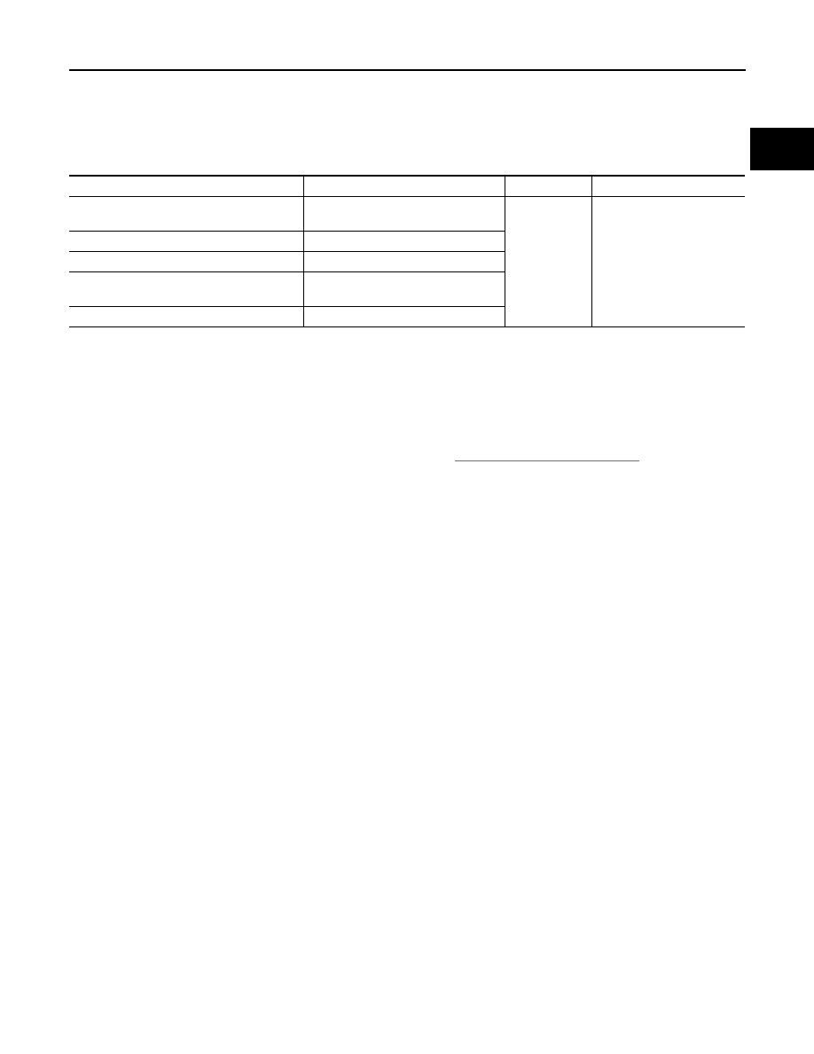
INPUT/OUTPUT SIGNAL CHART

*: This signal is sent to the ECM through CAN communication line.

SYSTEM DESCRIPTION

If the engine speed is above 1,800 rpm under no load (for example, the shift position is neutral and engine
speed is over 1,800 rpm) fuel will be cut off after some time. The exact time when the fuel is cut off varies
based on engine speed.
Fuel cut will be operated until the engine speed reaches 1,500 rpm, then fuel cut will be cancelled.
NOTE:
This function is different from deceleration control listed under 

EC-484, "System Description"

.

Sensor

Input Signal to ECM

ECM function

Actuator

Park/neutral position (PNP) switch (M/T)
TCM (A/T)

Neutral position

Fuel cut control

Fuel injector

Accelerator pedal position sensor

Accelerator pedal position

Engine coolant temperature sensor

Engine coolant temperature

Crankshaft position sensor (POS)
Camshaft position sensor (PHASE)

Engine speed

Wheel sensor

Vehicle speed*

EC-948

< PRECAUTION >

[VQ40DE]

PRECAUTIONS

PRECAUTION

PRECAUTIONS

Precaution for Supplemental Restraint System (SRS) "AIR BAG" and "SEAT BELT 
PRE-TENSIONER"

INFOID:0000000005273904

The Supplemental Restraint System such as “AIR BAG” and “SEAT BELT PRE-TENSIONER”, used along
with a front seat belt, helps to reduce the risk or severity of injury to the driver and front passenger for certain
types of collision. This system includes seat belt switch inputs and dual stage front air bag modules. The SRS
system uses the seat belt switches to determine the front air bag deployment, and may only deploy one front
air bag, depending on the severity of a collision and whether the front occupants are belted or unbelted.
Information necessary to service the system safely is included in the SRS and SB section of this Service Man-
ual.

WARNING:

• To avoid rendering the SRS inoperative, which could increase the risk of personal injury or death in

the event of a collision which would result in air bag inflation, all maintenance must be performed by
an authorized NISSAN/INFINITI dealer.

• Improper maintenance, including incorrect removal and installation of the SRS, can lead to personal

injury caused by unintentional activation of the system. For removal of Spiral Cable and Air Bag
Module, see the SRS section.

• Never use electrical test equipment on any circuit related to the SRS unless instructed to in this Ser-

vice Manual. SRS wiring harnesses can be identified by yellow and/or orange harnesses or harness
connectors.

Precaution for Procedure without Cowl Top Cover

INFOID:0000000005273905

When performing the procedure after removing cowl top cover, cover
the lower end of windshield with urethane, etc.

On Board Diagnosis (OBD) System of Engine and A/T

INFOID:0000000005273906

The ECM has an on board diagnostic system. It will illuminate the malfunction indicator lamp (MIL) to warn the
driver of a malfunction causing emission deterioration.

CAUTION:

• Always turn the ignition switch OFF and disconnect the negative battery cable before any repair or

inspection work. The open/short circuit of related switches, sensors, solenoid valves, etc. will cause
the MIL to illuminate.

• Always connect and lock the connectors securely after work. A loose (unlocked) connector will

cause the MIL to illuminate due to the open circuit. (Be sure the connector is free from water, grease,
dirt, bent terminals, etc.)

• Certain systems and components, especially those related to OBD, may use a new style slide-lock-

ing type harness connector. For description and how to disconnect, refer to 

PG-74, "Description"

.

• Always route and secure the harnesses properly after work. The interference of the harness with a

bracket, etc. may cause the MIL to illuminate due to the short circuit.

• Always connect rubber tubes properly after work. A misconnected or disconnected rubber tube may

cause the MIL to illuminate due to the malfunction of the EVAP system or fuel injection system, etc.

• Always erase the unnecessary malfunction information (repairs completed) from the ECM and TCM

(Transmission control module) before returning the vehicle to the customer.

PIIB3706J

PRECAUTIONS

EC-949

< PRECAUTION >

[VQ40DE]

C

D

E

F

G

H

I

J

K

L

M

A

EC

N

P

O

Precaution

INFOID:0000000005273907

• Always use a 12 volt battery as power source.
• Never attempt to disconnect battery cables while engine is

running.

• Before connecting or disconnecting the ECM harness con-

nector, turn ignition switch OFF and disconnect negative bat-
tery cable. Failure to do so may damage the ECM because
battery voltage is applied to ECM even if ignition switch is
turned OFF.

• Before removing parts, turn ignition switch OFF and then dis-

connect negative battery cable.

• Never disassemble ECM.
• If a battery cable is disconnected, the memory will return to the ECM value.

The ECM will now start to self-control at its initial value. Engine operation can vary slightly when the
terminal is disconnected. However, this is not an indication of a malfunction. Never replace parts
because of a slight variation.

• If the battery is disconnected, the following emission-related diagnostic information will be lost

within 24 hours.

Diagnostic trouble codes
1st trip diagnostic trouble codes
Freeze frame data
1st trip freeze frame data
System readiness test (SRT) codes
Test values
- <Frexible Fuel Vehicle>

Presumed ethanol mixture ratio

• When connecting ECM harness connector, fasten it securely

with levers as far as they will go as shown in the figure.

• When connecting or disconnecting pin connectors into or

from ECM, take care not to damage pin terminals (bend or
break).
Check that there are not any bends or breaks on ECM pin ter-
minal, when connecting pin connectors.

• Securely connect ECM harness connectors.

A poor connection can cause an extremely high (surge) volt-
age to develop in coil and condenser, thus resulting in dam-
age to ICs.

• Keep engine control system harness at least 10 cm (4 in) away

from adjacent harness, to prevent engine control system mal-
functions due to receiving external noise, degraded operation
of ICs, etc.

• Keep engine control system parts and harness dry.

SEF289H

PBIB1512E

PBIB0090E

EC-950

< PRECAUTION >

[VQ40DE]

PRECAUTIONS

• Before replacing ECM, perform “ECM Terminals and Refer-

ence Value” inspection and check ECM functions properly.
Refer to 

EC-888, "ECM Terminal and Reference Value"

.

• Handle mass air flow sensor carefully to avoid damage.
• Never clean mass air flow sensor with any type of detergent.
• Never disassemble electric throttle control actuator.
• Even a slight leak in the air intake system can cause serious

incidents.

• Never shock or jar the camshaft position sensor (PHASE),

crankshaft position sensor (POS).

• After performing each TROUBLE DIAGNOSIS, perform DTC

Confirmation Procedure or Overall Function Check.
The DTC should not be displayed in the DTC Confirmation
Procedure if the repair is completed. The Overall Function
Check should be a good result if the repair is completed.

• When measuring ECM signals with a circuit tester, never allow

the two tester probes to contact.
Accidental contact of probes will cause a short circuit and
damage the ECM power transistor.

• Never use ECM ground terminals when measuring input/out-

put voltage. Doing so may result in damage to the ECM's tran-
sistor. Use a ground other than ECM terminals, such as the
ground.

• B1 indicates the bank 1, B2 indicates the bank 2 as shown in

the figure.

MEF040D

SEF217U

SEF348N

SEC893C


Content   ..  562  563  564  565   ..