Nissan Frontier D40. Manual - part 528
P1572 ASCD BRAKE SWITCH
EC-803
< COMPONENT DIAGNOSIS >
[VQ40DE]
C
D
E
F
G
H
I
J
K
L
M
A
EC
N
P
O
2.
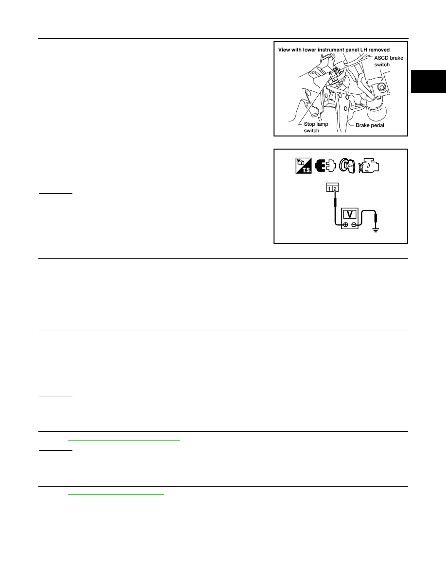
Disconnect stop lamp switch harness connector.
3.
Check voltage between stop lamp switch terminal 2 and ground
with CONSULT-III or tester.
OK or NG
OK
>> GO TO 12.
NG
>> GO TO 11.
11.
DETECT MALFUNCTIONING PART
Check the following.
• Fuse block (J/B) connector F160
• 10 A fuse (No.20)
• Harness for open or short between stop lamp switch and battery
>> Repair open circuit or short to ground or short to power in harness or connectors.
12.
CHECK STOP LAMP SWITCH INPUT SIGNAL CIRCUIT FOR OPEN AND SHORT
1.
Disconnect ECM harness connector.
2.
Check harness continuity between ECM terminal 101 and stop lamp switch terminal 2.
Refer to Wiring Diagram.
3.
Also check harness for short to ground and short to power.
OK or NG
OK
>> GO TO 13.
NG
>> Repair open circuit or short to ground or short to power in harness or connectors.
13.
CHECK STOP LAMP SWITCH
EC-803, "Component Inspection"
OK or NG
OK
>> GO TO 14.
NG
>> Replace stop lamp switch.
14.
CHECK INTERMITTENT INCIDENT
GI-46, "Intermittent Incident"
.
>> INSPECTION END
Component Inspection
INFOID:0000000005273806
ASCD BRAKE SWITCH
BBIA0560E
Voltage: Battery voltage
MBIB1407E
Continuity should exist.