Nissan Frontier D40. Manual - part 478


  Index      Nissan     Nissan Frontier D40 (2010 year) - Service and Repair Manual


Search            


Content   ..  476  477  478  479   ..


Nissan Frontier D40. Manual - part 478


P0131, P0151 A/F SENSOR 1

EC-603

< COMPONENT DIAGNOSIS >

[VQ40DE]

C

D

E

F

G

H

I

J

K

L

M

A

EC

N

P

O

5.

Turn ignition switch ON.

6.

Turn ignition switch OFF and wait at least 10 seconds.

7.

Restart engine.

8.

Drive and accelerate vehicle to more than 40 km/h (25 MPH) within 20 seconds after restarting engine.

9.

Maintain the following conditions for about 20 consecutive seconds.

NOTE:
• Keep the accelerator pedal as steady as possible during cruising.
• If this procedure is not completed within 1 minute after restarting engine at step 4, return to step

4.

10. Check 1st trip DTC.
11. If 1st trip DTC is displayed, go to 

EC-603, "Diagnosis Procedure"

.

 WITH GST

Follow the procedure “WITH CONSULT-III” above.

Diagnosis Procedure

INFOID:0000000005273578

1.

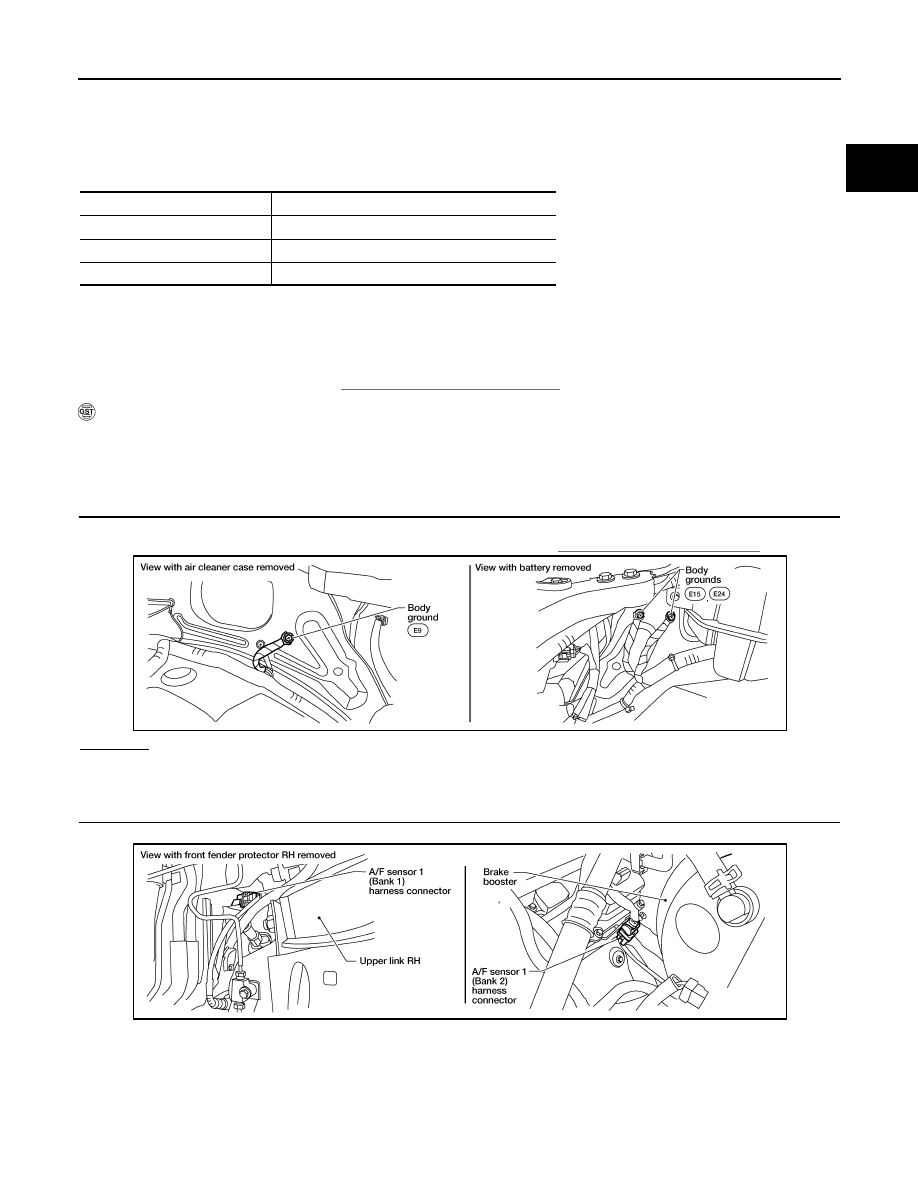
CHECK GROUND CONNECTIONS

1.

Turn ignition switch OFF.

2.

Loosen and retighten three ground screws on the body. Refer to 

EC-549, "Ground Inspection"

.

OK or NG

OK

>> GO TO 2.

NG

>> Repair or replace ground connections.

2.

CHECK AIR FUEL RATIO (A/F) SENSOR 1 POWER SUPPLY CIRCUIT

1.

Disconnect A/F sensor 1 harness connector.

2.

Turn ignition switch ON.

ENG SPEED

1,000 - 3,200 rpm

VHCL SPEED SE

More than 40 km/h (25 MPH)

B/FUEL SCHDL

1.5 - 9.0 msec

Gear position

Suitable position

BBIA0539E

BBIA0544E

EC-604

< COMPONENT DIAGNOSIS >

[VQ40DE]

P0131, P0151 A/F SENSOR 1

3.

Check voltage between A/F sensor 1 terminal 4 and ground with
CONSULT-III or tester.

OK or NG

OK

>> GO TO 4.

NG

>> GO TO 3.

3.

DETECT MALFUNCTIONING PART

Check the following.
• Harness connectors E2, F32 
• IPDM E/R connector E119
• 15 A fuse (No.54)
• Harness for open or short between A/F sensor 1 and fuse

>> Repair or replace harness or connectors.

4.

CHECK A/F SENSOR 1 INPUT SIGNAL CIRCUIT FOR OPEN AND SHORT

1.

Turn ignition switch OFF.

2.

Disconnect ECM harness connector.

3.

Check harness continuity between A/F sensor 1 terminal and ECM terminal as follows.
Refer to Wiring Diagram.

4.

Check harness continuity between the following terminals and ground.
Refer to Wiring Diagram.

5.

Also check harness for short to power.

OK or NG

OK

>> GO TO 5.

NG

>> Repair open circuit or short to ground or short to power in harness or connectors.

5.

CHECK INTERMITTENT INCIDENT

Perform 

GI-46, "Intermittent Incident"

.

OK or NG

OK

>> GO TO 6.

NG

>> Repair or replace.

Voltage: Battery voltage

PBIB3308E

A/F sensor 1 terminal

ECM terminal

Bank1

1

35

2

56

Bank 2

1

16

2

75

Continuity should exist.

Bank 1

Bank 2

A/F sensor 1 terminal

ECM terminal

A/F sensor 1 terminal

ECM terminal

1

35

1

16

2

56

2

75

Continuity should not exist.

P0131, P0151 A/F SENSOR 1

EC-605

< COMPONENT DIAGNOSIS >

[VQ40DE]

C

D

E

F

G

H

I

J

K

L

M

A

EC

N

P

O

6.

REPLACE A/F SENSOR 1

Replace malfunctioning A/F sensor 1.

CAUTION:

• Discard any A/F sensor which has been dropped from a height of more than 0.5 m (19.7 in) onto a

hard surface such as a concrete floor; use a new one.

• Before installing new A/F sensor, clean exhaust system threads using Heated Oxygen Sensor

Thread Cleaner tool J-43897-18 or J-43897-12 and approved anti-seize lubricant.

>> INSPECTION END

EC-606

< COMPONENT DIAGNOSIS >

[VQ40DE]

P0132, P0152 A/F SENSOR 1

P0132, P0152 A/F SENSOR 1

Component Description

INFOID:0000000005273579

The air fuel ratio (A/F) sensor 1 is a planar one-cell limit current sen-
sor. The sensor element of the A/F sensor 1 is composed an elec-
trode layer, which transports ions. It has a heater in the element.
The sensor is capable of precise measurement   = 1, but also in the
lean and rich range. Together with its control electronics, the sensor
outputs a clear, continuous signal throughout a wide   range.
The exhaust gas components diffuse through the diffusion layer at
the sensor cell. An electrode layer is applied voltage, and this current
relative oxygen density in lean. Also this current relative hydrocar-
bon density in rich.
Therefore, the A/F sensor 1 is able to indicate air fuel ratio by this
electrode layer of current. In addition, a heater is integrated in the
sensor to ensure the required operating temperature of about 800

°

C

(1,472

°

F).

On Board Diagnosis Logic

INFOID:0000000005273580

To judge the malfunction, the diagnosis checks that the A/F signal computed by ECM from the A/F sensor 1
signal is not inordinately high.

DTC Confirmation Procedure

INFOID:0000000005273581

NOTE:
If DTC Confirmation Procedure has been previously conducted, always perform the following before conduct-
ing the next step.

1.

Turn ignition switch OFF and wait at least 10 seconds.

2.

Turn ignition switch ON.

3.

Turn ignition switch OFF and wait at least 10 seconds.

TESTING CONDITION:
Before performing the following procedure, confirm that battery voltage is more than 11V at idle.

 WITH CONSULT-III

1.

Start engine and warm it up to normal operating temperature.

2.

Select “A/F SEN1 (B1)” or “A/F SEN1 (B2)” in “DATA MONITOR” mode with CONSULT-III.

3.

Check “A/F SEN1 (B1)” or “A/F SEN1 (B2)” indication.
If the indication is constantly approx. 5V, go to 

EC-607, "Diagnosis Procedure"

.

If the indication is not constantly approx. 5V, go to next step.

4.

Turn ignition switch OFF and wait at least 10 seconds.

PBIB3353E

PBIB3354E

DTC No.

Trouble diagnosis name

DTC detecting condition

Possible Cause

P0132
0132
(Bank 1)

Air fuel ratio (A/F) sensor 1 
circuit high voltage

• The A/F signal computed by ECM from the A/F 

sensor 1 signal is constantly approx. 5V.

• Harness or connectors

(The A/F sensor 1 circuit is open or 
shorted.)

• A/F sensor 1

P0152
0152
(Bank 2)


Content   ..  476  477  478  479   ..