Nissan Frontier D40. Manual - part 465
U1001 CAN COMM CIRCUIT
EC-551
< COMPONENT DIAGNOSIS >
[VQ40DE]
C
D
E
F
G
H
I
J
K
L
M
A
EC
N
P
O
U1001 CAN COMM CIRCUIT
Description
INFOID:0000000005273502
CAN (Controller Area Network) is a serial communication line for real time application. It is an on-vehicle mul-
tiplex communication line with high data communication speed and excellent error detection ability. Many elec-
tronic control units are equipped onto a vehicle, and each control unit shares information and links with other
control units during operation (not independent). In CAN communication, control units are connected with 2
communication lines (CAN H line, CAN L line) allowing a high rate of information transmission with less wiring.
Each control unit transmits/receives data but selectively reads required data only.
On Board Diagnosis Logic
INFOID:0000000005273503
The MIL will not illuminate for this diagnosis.
DTC Confirmation Procedure
INFOID:0000000005273504
1.
Turn ignition switch ON and wait at least 3 seconds.
2.
Check 1st trip DTC.
3.
If 1st trip DTC is detected, go to
Diagnosis Procedure
INFOID:0000000005273505
LAN-48, "CAN System Specification Chart"
.
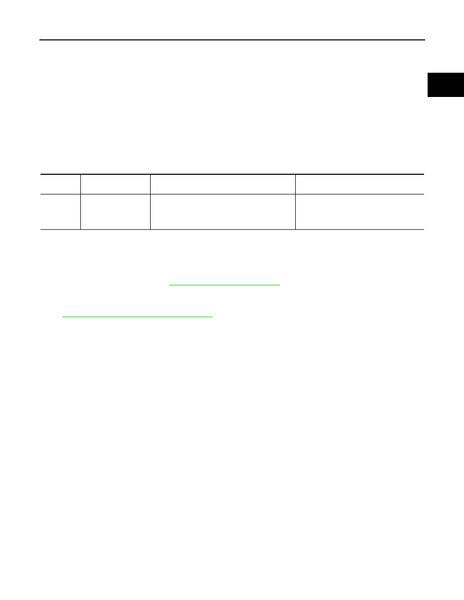
DTC No.
Trouble diagnosis
name
DTC detecting condition
Possible cause
U1001
1001
CAN communication
line
• When ECM is not transmitting or receiving
CAN communication signal other than OBD
(emission-related diagnosis) for 2 seconds or
more.
• Harness or connectors
(CAN communication line is open or
shorted)