Nissan Frontier D40. Manual - part 454


  Index      Nissan     Nissan Frontier D40 (2010 year) - Service and Repair Manual


Search            


Content   ..  452  453  454  455   ..


Nissan Frontier D40. Manual - part 454


ON BOARD DIAGNOSTIC (OBD) SYSTEM

EC-507

< FUNCTION DIAGNOSIS >

[VQ40DE]

C

D

E

F

G

H

I

J

K

L

M

A

EC

N

P

O

• Sea level
• Flat road
• Ambient air temperature: 20 - 30

°

C (68 - 86

°

F)

• Diagnosis is performed as quickly as possible under normal conditions.

Under different conditions [For example: ambient air temperature other than 20 - 30

°

C (68 - 86

°

F)], diagno-

sis may also be performed.

Pattern 1:
• The engine is started at the engine coolant temperature of 

10 to 35

°

C (14 to 95

°

F)

(where the voltage between the ECM terminal 73 and ground is 3.0 - 4.3V).

• The engine must be operated at idle speed until the engine coolant temperature is greater than 70

°

C

(158

°

F) (where the voltage between the ECM terminal 73 and ground is lower than 1.4V).

• The engine is started at the fuel tank temperature of warmer than 0

°

C (32

°

F) (where the voltage

between the ECM terminal 107 and ground is less than 4.1V).

Pattern 2:
• When steady-state driving is performed again even after it is interrupted, each diagnosis can be conducted.

In this case, the time required for diagnosis may be extended.
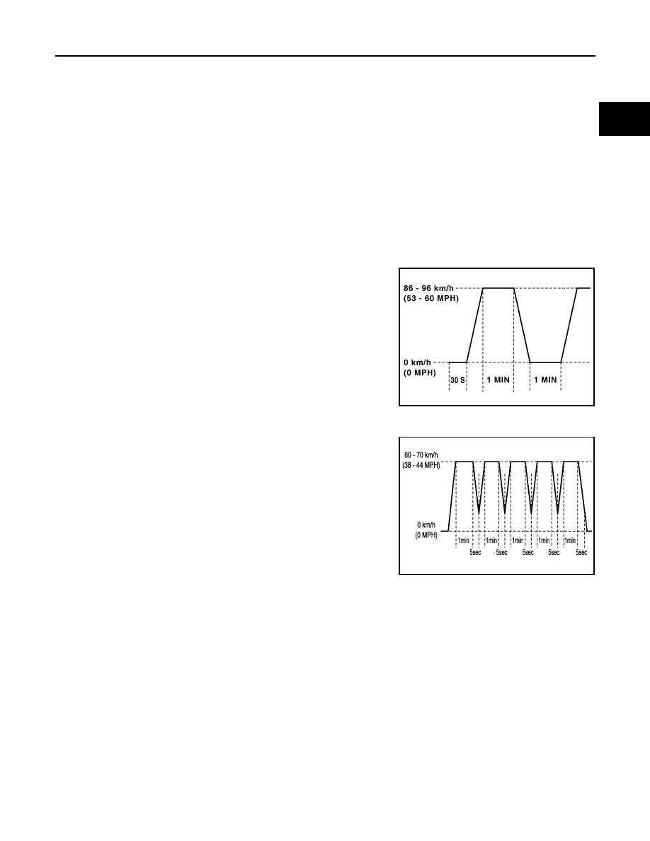
Pattern 3:
• Operate vehicle following the driving pattern shown in the figure.
• Replace the accelerator pedal during decelerating vehicle speed

from 90km/h (56MPH) to 0km/h (0MPH).

Pattern 4:
• Operate vehicle, following the driving pattern shown in the figure.
- Drive the vehicle in a proper gear at 60 km/h (38 MPH) and main-

tain the speed.

- Release the accelerator pedal fully at least 5 seconds.
- Repeat the above two steps at least 5 times.

Pattern 5:
• The accelerator pedal must be held very steady during steady-state driving.
• If the accelerator pedal is moved, the test must be conducted all over again.
*1: Depress the accelerator pedal until vehicle speed is 90 km/h (56 MPH), then release the accelerator pedal
and keep it released for more than 10 seconds. Depress the accelerator pedal until vehicle speed is 90 km/h
(56 MPH) again.
*2: Checking the vehicle speed with GST is advised.

Suggested Transmission Gear Position for A/T Models
Set the selector lever in the D position with the overdrive switch turned ON.
Suggested Upshift Speeds for M/T Models
Shown below are suggested vehicle speeds vehicle speeds for shifting into a higher gear. These suggestions
relate to fuel economy and vehicle performance. Actual upshift speeds will vary according to road conditions,
the weather and individual driving habits.

PBIB2244E

JSBIA0160GB

EC-508

< FUNCTION DIAGNOSIS >

[VQ40DE]

ON BOARD DIAGNOSTIC (OBD) SYSTEM

Suggested Maximum Speed in Each Gear
Downshift to a lower gear if the engine is not running smoothly, or if you need to accelerate.
Do not exceed the maximum suggested speed (shown below) in any gear. For level road driving, use the high-
est gear suggested for that speed. Always observe posted speed limits and drive according to the road condi-
tions to ensure sage operation. Do not over-rev the engine when shifting to a lower gear as it may cause
engine damage or loss of vehicle control.

PERMANENT DIAGNOSTIC TROUBLE CODE (PERMANENT DTC)

Permanent DTC is defined in SAE J1979/ISO 15031-5 Service $0A.
ECM stores a DTC issuing a command of turning on MIL as a permanent DTC and keeps storing the DTC as
a permanent DTC until ECM judges that there is no presence of malfunction.
Permanent DTCs cannot be erased by using the Erase function of CONSULT-III or Generic Scan Tool (GST)
and by disconnecting the battery to shut off power to ECM. This prevents a vehicle from passing the state
emission inspection without repairing a malfunctioning part.
When not passing the state emission inspection due to more than one permanent DTC, permanent DTCs
should be erased, referring to this manual.
NOTE:
• The important items in state emission inspection are that MIL is not ON, SRT test items are set, and perma-

nent DTCs are not included.

• Permanent DTCs do not apply for regions that permanent DTCs are not regulated by law.

Permanent DTC Item

For permanent DTC items, MIL turns ON. Refer to 

EC-501, "Emission-related Diagnostic Information"

, “EMIS-

SION-RELATED DIAGNOSTIC INFORMATION ITEMS”.

Permanent DTC Set Timing

The setting timing of permanent DTC is stored in ECM with the lighting of MIL when a DTC is confirmed.

Permanent DTC Service Procedure

For normal acceleration in altitude areas

[less than 1,219 m (4,000 ft)]:

For quick acceleration in low altitude

areas and high altitude areas

[over 1,219 m (4,000 ft)]:

Gear change

ACCEL shift point km/h (MPH)

CRUISE shift point km/h (MPH)

km/h (MPH)

1st to 2nd

21 (13)

17 (11)

24 (15)

2nd to 3rd

38 (24)

27 (17)

40 (25)

3rd to 4th

53 (33)

40 (25)

64 (40)

4th to 5th

69 (43)

51 (32)

72 (45)

6th

77 (48)

72 (45)

80 (50)

Gear

km/h (MPH)

1st

56 (35)

2nd

96 (60)

3rd

136 (85)

4th

5th

6th

ON BOARD DIAGNOSTIC (OBD) SYSTEM

EC-509

< FUNCTION DIAGNOSIS >

[VQ40DE]

C

D

E

F

G

H

I

J

K

L

M

A

EC

N

P

O

How to Display Permanent DTC Status

WITH CONSULT-III

1.

Turn ignition switch OFF and wait at least 10 seconds.

2.

Turn ignition switch ON.

3.

Turn ignition switch OFF and wait at least 10 seconds.

4.

Turn ignition switch ON.

5.

Select “PERMANENT DTC STATUS” in “DTC & SRT CONFIRMATION” mode with CONSULT-III.
NOTE:
Permanent DTCs stored in ECM memory are displayed on the CONSULT-III screen to show if a driving
pattern required for erasing permanent DTCs is complete (CMPLT) or incomplete (INCMP).

CAUTION:

Since the “PERMANENT DTC STATUS” screen displays the previous trip information, repeat the
following twice to update the information: “Ignition switch OFF”, “Wait for more than 10 seconds”
and “Ignition switch ON”.

JSBIA0066GB

JSBIA0062GB

EC-510

< FUNCTION DIAGNOSIS >

[VQ40DE]

ON BOARD DIAGNOSTIC (OBD) SYSTEM

WITH GST

1.

Turn ignition switch OFF and wait at least 10 seconds.

2.

Turn ignition switch ON.

3.

Turn ignition switch OFF and wait at least 10 seconds.

4.

Turn ignition switch ON.

5.

Select Service $0A with GST (Generic Scan Tool).

TEST VALUE AND TEST LIMIT

The following is the information specified in Service $06 of SAE J1979/ISO 15031-5.
The test value is a parameter used to determine whether a system/circuit diagnostic test is OK or NG while
being monitored by the ECM during self-diagnosis. The test limit is a reference value which is specified as the
maximum or minimum value and is compared with the test value being monitored.
These data (test value and test limit) are specified by On Board Monitor ID(OBDMID), Test ID (TID), Unit and
Scaling ID and can be displayed on the GST screen.
The items of the test value and test limit will be displayed with GST screen which items are provided by the
ECM. (e.g., if the bank 2 is not applied on this vehicle, only the items of the bank 1 is displayed)


Content   ..  452  453  454  455   ..