Nissan Frontier D40. Manual - part 281
PROPELLER SHAFT
DLN-145
< REMOVAL AND INSTALLATION >
[PROPELLER SHAFT: 2S1330]
C
E
F
G
H
I
J
K
L
M
A
B
DLN
N
O
P
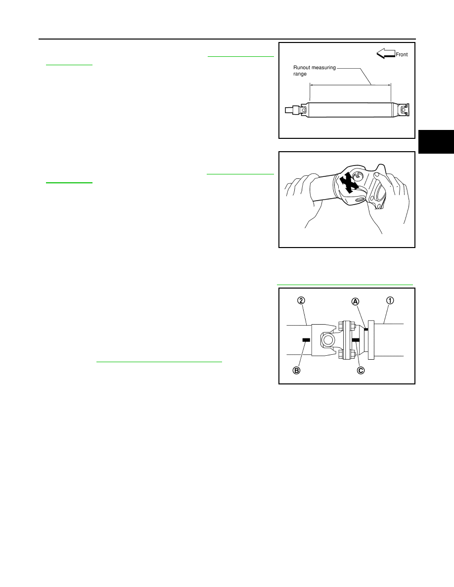
• Inspect the propeller shaft runout. If runout exceeds the limit,
replace the propeller shaft assembly. Refer to
• While holding the flange yoke on one side, check axial play of the
joint as shown. If the journal axial play exceeds the specification,
repair or replace the journal parts. Refer to
• Check the propeller shaft tube for dents or cracks. If damage is
detected, replace the propeller shaft assembly.
INSTALLATION
Installation is in the reverse order of removal.
• After installation, check for vibration by driving the vehicle. Refer to
DLN-142, "NVH Troubleshooting Chart"
.
• If propeller shaft assembly or final drive assembly has been
replaced, connect them as follows:
- Face companion flange mark (A) of the final drive (1) upward. With
the mark (A) faced upward, couple the propeller shaft and the final
drive so that the matching mark (B) of the propeller shaft (2) can be
positioned as closest as possible with the matching mark (C) of the
final drive companion flange.
- Tighten propeller shaft and final drive bolts and nuts to specifica-
tions. Refer to
DLN-144, "Removal and Installation"
.
CAUTION:
Do not reuse the bolts and nuts. Always install new ones.
LDIA0121E
LDIA0117E
PDIA0892J