Nissan Frontier D40. Manual - part 263
4WD WARNING LAMP DOES NOT TURN ON
DLN-73
< SYMPTOM DIAGNOSIS >
[TRANSFER: TX15B]
C
E
F
G
H
I
J
K
L
M
A
B
DLN
N
O
P
4WD WARNING LAMP DOES NOT TURN ON
Description
INFOID:0000000005275462
4WD warning lamp does not turn ON when turning ignition switch to ON.
Diagnosis Procedure
INFOID:0000000005275463
Regarding Wiring Diagram information, refer to
.
1.
CHECK TRANSFER CONTROL UNIT POWER SUPPLY AND GROUND CIRCUITS
.
Are the inspection results normal?
YES
>> GO TO 2.
NO
>> Perform repairs as necessary.
2.
CHECK COMBINATION METER POWER SUPPLY CIRCUIT
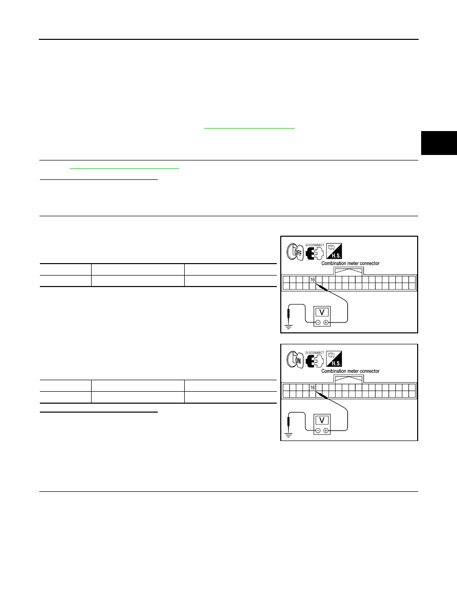
1.
Turn ignition switch “OFF”. (Stay for at least 5 seconds.)
2.
Disconnect combination meter harness connector.
3.
Check voltage between combination meter harness connector
terminals and ground.
4.
Turn ignition switch “ON”. (Do not start engine.)
5.
Check voltage between combination meter harness connector
terminals and ground.
Are the inspection results normal?
YES
>> GO TO 3.
NO
>>
Check the following. If any items are damaged, repair
or replace damaged parts.
• 10A fuse [No. 14, located in the fuse block (J/B)] or
ignition switch.
• Harness for short or open between ignition switch and combination meter harness connector
terminal 16
3.
CHECK HARNESS BETWEEN TRANSFER CONTROL UNIT AND COMBINATION METER
1.
Turn ignition switch “OFF”. (Stay for at least 5 seconds.)
Connector
Terminal
Voltage (Approx.)
M24
16 - Ground
0V
WDIA0178E
Connector
Terminal
Voltage (Approx.)
M24
16 - Ground
Battery voltage
WDIA0179E