Nissan Frontier D40. Manual - part 258
P1819 TRANSFER CONTROL DEVICE
DLN-53
< COMPONENT DIAGNOSIS >
[TRANSFER: TX15B]
C
E
F
G
H
I
J
K
L
M
A
B
DLN
N
O
P
4.
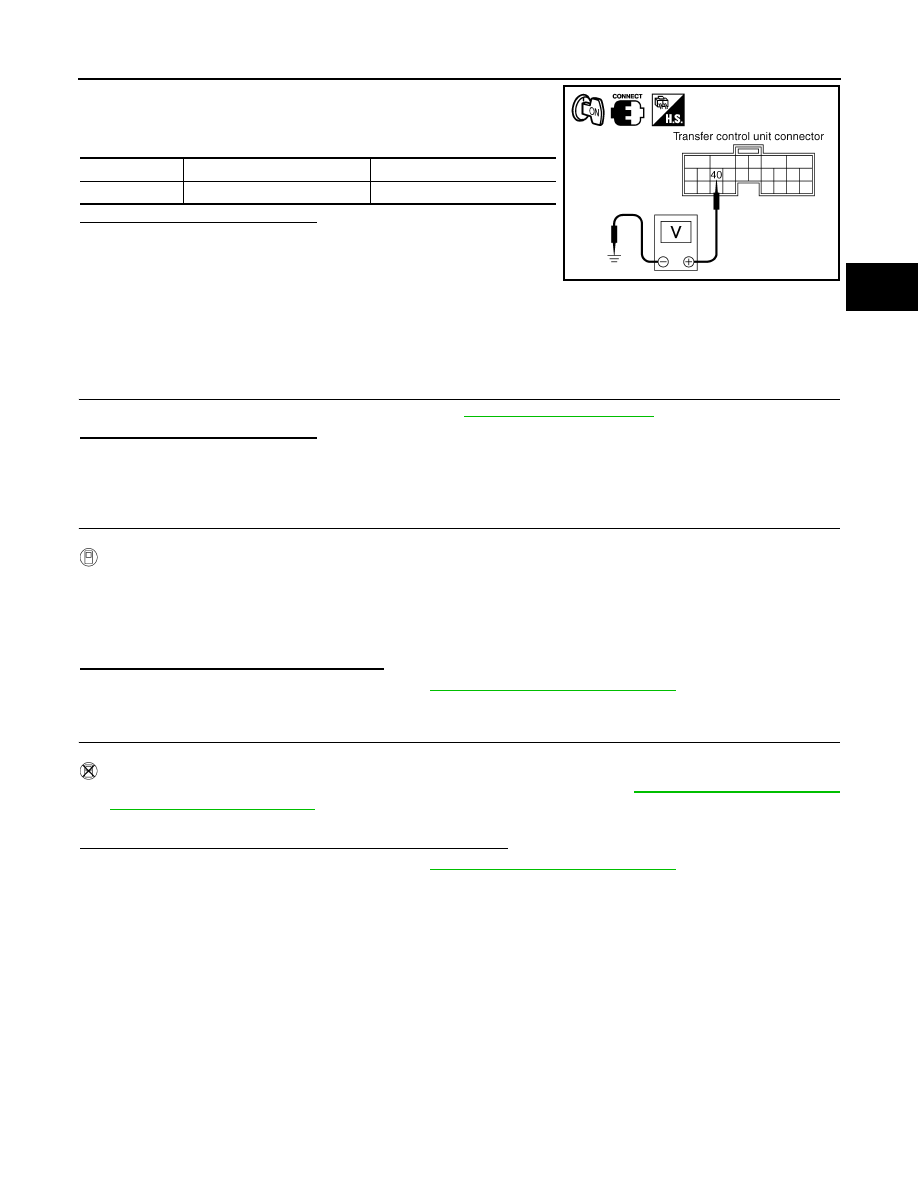
Turn ignition switch “ON”. (Do not start engine.)
5.
Check voltage between transfer control unit harness connector
terminal and ground.
Are the inspection results normal?
YES
>> GO TO 4.
NO
>>
Check the following. If any items are damaged, repair
or replace damaged parts.
• Harness for short or open between battery and trans-
fer shut off relay 2 harness connector E157 terminal 1.
• Harness for short or open between transfer shut off relay 2 harness connector E157 terminal 2
and transfer control unit harness connector M153 terminal 40.
• Transfer shut off relay 2.
4.
CHECK TRANSFER CONTROL UNIT
Check transfer control unit input/output signal. Refer to
Are the inspection results normal?
YES
>> GO TO 5 (With CONSULT-III) or GO TO 6 (Without CONSULT-III).
NO
>> Check transfer control unit pin terminals for damage or loose connection with harness connector.
If any items are damaged, repair or replace damaged parts.
5.
PERFORM SELF-DIAGNOSIS (WITH CONSULT-III)
With CONSULT-III
1.
Turn ignition switch “ON”. (Do not start engine.)
2.
Select “SELF-DIAG RESULTS” mode for “ALL MODE AWD/4WD” with CONSULT-III.
3.
Touch “ERASE”.
4.
Turn ignition switch “OFF” and wait at least 10 seconds.
5.
Perform the self-diagnosis again.
Is the “SHIFT ACT CIR [P1819]” displayed?
YES
>> Replace transfer control unit. Refer to
DLN-94, "Removal and Installation"
.
NO
>> Inspection End.
6.
PERFORM SELF-DIAGNOSIS (WITHOUT CONSULT-III)
Without CONSULT-III
1.
Perform the self-diagnosis and then erase self-diagnostic results. Refer to
2.
Perform the self-diagnosis again.
Do the self-diagnostic results indicate transfer control device?
YES
>> Replace transfer control unit. Refer to
DLN-94, "Removal and Installation"
.
NO
>> Inspection End.
Connector
Terminal
Voltage (Approx.)
M153
40 - Ground
0V
SDIA2820E