Nissan Frontier D40. Manual - part 218
DOOR LOCK AND UNLOCK SWITCH
DLK-35
< COMPONENT DIAGNOSIS >
C
D
E
F
G
H
I
J
L
M
A
B
DLK
N
O
P
CREW CAB : Diagnosis Procedure
INFOID:0000000005274513
Regarding Wiring Diagram information, refer to
DLK-84, "Wiring Diagram—POWER DOOR LOCK SYSTEM
1.
CHECK DOOR LOCK/UNLOCK SWITCH INPUT SIGNAL
With CONSULT-III
Check door lock/unlock switch ("CDL LOCK SW", "CDL UNLOCK SW") in DATA MONITOR mode in CON-
SULT–III. Refer to
DLK-20, "DOOR LOCK : CONSULT-III Function (BCM - DOOR LOCK)"
.
• When door lock/unlock switch is turned to LOCK:
• When door lock/unlock switch is turned to UNLOCK:
Without CONSULT-III
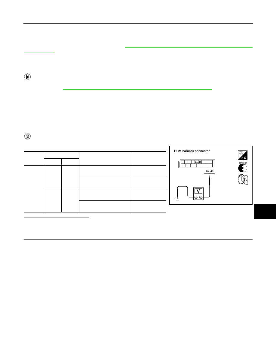
Check voltage between BCM connector M19 terminals 45, 46 and ground.
Is the inspection result normal?
YES
>> Door lock/unlock switch circuit is OK.
NO
>> GO TO 2
2.
CHECK DOOR LOCK/UNLOCK SWITCH
1.
Turn ignition switch OFF.
2.
Disconnect door lock/unlock switch.
CDL LOCK SW
: ON
CDL UNLOCK SW
: ON
Connec-
tor
Terminals
Condition
Voltage (V)
(Approx.)
(+)
(–)
M19
46
Ground
Door lock/unlock switch is
neutral.
Battery voltage
Door lock/unlock switch is
turned to UNLOCK.
0
45
Ground
Door lock/unlock switch is
neutral.
Battery voltage
Door lock/unlock switch is
turned to LOCK.
0
LIIA1351E