Nissan Frontier D40. Manual - part 190


  Index      Nissan     Nissan Frontier D40 (2010 year) - Service and Repair Manual


Search            


Content   ..  188  189  190  191   ..


Nissan Frontier D40. Manual - part 190


WATER PUMP

CO-21

< ON-VEHICLE REPAIR >

[QR25DE]

C

D

E

F

G

H

I

J

K

L

M

A

CO

N

P

O

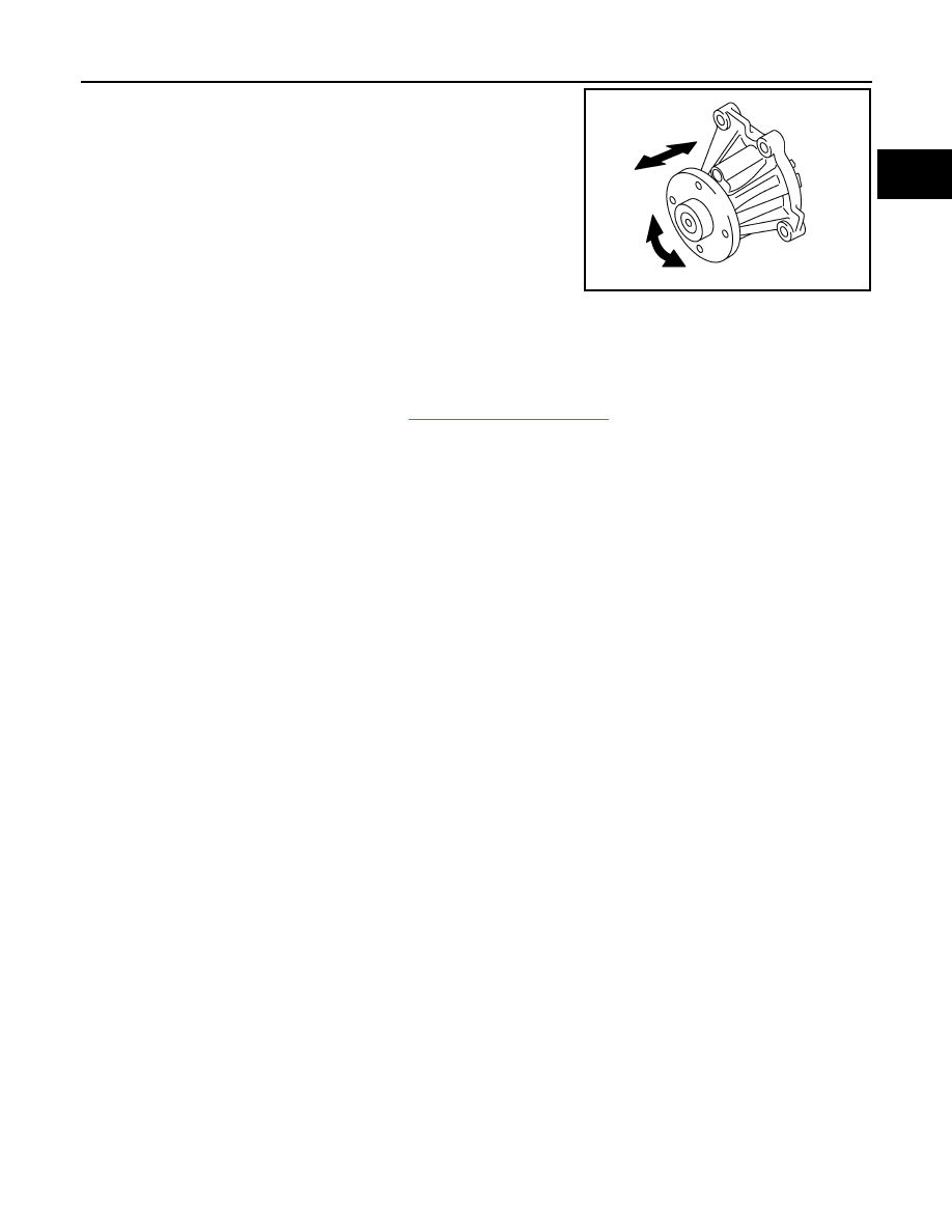
• Visually check if there is no significant dirt or rusting on water

pump body and vane.

• Make sure that there is no looseness in vane shaft, and that it turns

smoothly when rotated by hand.

• Replace water pump, if necessary.

INSTALLATION

Installation is in the reverse order of removal.
• When inserting heater pipe end into water pump and thermostat housing, apply a neutral detergent to O-

ring. Then insert it immediately.

INSPECTION AFTER INSTALLATION

• Check for leaks of engine coolant. Refer to 

CO-11, "System Inspection"

.

• Start and warm up the engine. Visually check if there is no leaks of engine coolant.

PBIC3011E

CO-22

< ON-VEHICLE REPAIR >

[QR25DE]

THERMOSTAT AND THERMOSTAT HOUSING

THERMOSTAT AND THERMOSTAT HOUSING

Exploded View

INFOID:0000000005276092

Removal and Installation Thermostat

INFOID:0000000005276093

REMOVAL

1.

Drain engine coolant from the radiator. Refer to 

CO-12, "Changing Engine Coolant"

 and 

EM-78,

"Exploded View"

.

CAUTION:

• Perform this step when the engine is cold.
• Do not spill engine coolant on drive belt.

2.

Remove the air duct. Refer to 

EM-25, "Exploded View"

.

3.

Disconnect radiator hose (lower) at water inlet side. Refer to 

CO-16, "Exploded View"

.

4.

Remove water inlet and thermostat.

INSPECTION AFTER REMOVAL

1.

Gasket

2.

Water outlet

3.

Water pump pulley

4.

Water pump

5.

Thermostat

6.

O-ring

7.

Water inlet

8.

Water pump and thermostat housing 9.

Heater pipe

10. Water hose

11.

Water hose

12. Heater outlet

13. Engine coolant temperature sensor

14. Water control valve

A.

To heater

B.

To electric throttle control actuator

C.

To oil cooler

Front

AWBIA0868GB

THERMOSTAT AND THERMOSTAT HOUSING

CO-23

< ON-VEHICLE REPAIR >

[QR25DE]

C

D

E

F

G

H

I

J

K

L

M

A

CO

N

P

O

• Place a thread so that it is caught in the valve of the thermostat.

Immerse fully in a container filled with water. Heat while stirring.

• The valve opening temperature is the temperature at which the

valve opens and falls from the thread.

• Continue heating. Check the full-open lift amount.

NOTE:
The full-open lift amount standard temperature for water control
valve is the reference value.

• After checking the full-open lift amount, lower the water tempera-

ture and check the valve closing temperature. 

Standard:

• If out of the standard, replace thermostat.

INSTALLATION

Installation is in the reverse order of removal.

Thermostat

• Install thermostat by making rubber ring (1) groove fit to thermostat

flange (A) around the whole circumference.

• Install thermostat with jiggle valve (A) facing upwards. The position

deviation may be within the range of 20

°

 (b).

INSPECTION AFTER INSTALLATION

• Check for leaks of engine coolant. Refer to 

CO-11, "System Inspection"

.

• Start and warm up the engine. Visually check if there is no leaks of engine coolant.

SLC252B

Items

Thermostat

Valve opening temperature

80.5 - 83.5

°

C (177 - 182

°

F)     

Full-open lift amount

8 mm/ 95

°

C (0.315 in/ 203

°

F)

Valve closing temperature

77

°

C (171

°

F) 

PBIC3317J

JPBIA2314ZZ

CO-24

< ON-VEHICLE REPAIR >

[QR25DE]

THERMOSTAT AND THERMOSTAT HOUSING

Exploded View

INFOID:0000000005276094

Removal and Installation Water Pump and Thermostat Housing

INFOID:0000000005276095

REMOVAL

1.

Drain engine coolant from the radiator. Refer to 

CO-12, "Changing Engine Coolant"

.

2.

Remove water pump. Refer to 

CO-20

3.

Remove radiator hose (lower) at water inlet. 

4.

Remove thermostat. Refer to 

CO-22, "Removal and Installation Thermostat"

.

5.

Remove exhaust manifold cover. Refer to 

EM-30, "Exploded View"

.

6.

Remove oil level gauge and oil level gauge guide. Refer to 

EM-78, "Exploded View"

.

CAUTION:

Plug the oil level gauge guide opening to prevent foreign materials from entering oil pan.

7.

Remove A/C compressor, if equipped, and position aside. Refer to 

HA-28, "Removal and Installation for

Compressor"

.

8.

Disconnect electric throttle control actuator, oil cooler and heater hose from heater pipe.

9.

Remove bolt for heater pipe at water pump and thermostat housing.

10. Disconnect heater pipe from water pump and thermostat housing.

11. Remove water pump and thermostat housing. 

INSTALLATION

Installation is in the reverse order of removal.

1.

Gasket

2.

Water outlet

3.

Water pump pulley

4.

Water pump

5.

Thermostat

6.

O-ring

7.

Water inlet

8.

Water pump and thermostat housing 9.

Heater pipe

10. Water hose

11.

Water hose

12. Heater outlet

13. Engine coolant temperature sensor

14. Water control valve

A.

To heater

B.

To electric throttle control actuator

C.

To oil cooler

Front

AWBIA0868GB


Content   ..  188  189  190  191   ..