Nissan Frontier D40. Manual - part 174
CHG
CHARGING SYSTEM
CHG-5
< FUNCTION DIAGNOSIS >
C
D
E
F
G
H
I
J
K
L
B
A
O
P
N
FUNCTION DIAGNOSIS
CHARGING SYSTEM
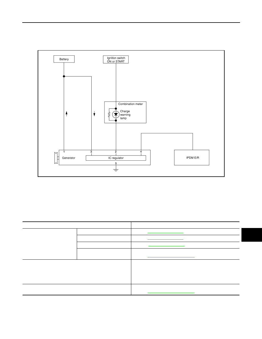
System Diagram
INFOID:0000000005272436
System Description
INFOID:0000000005272437
The generator provides DC voltage to operate the vehicle's electrical system and to keep the battery charged.
The voltage output is controlled by the IC regulator.
Component Description
INFOID:0000000005272438
ALMIA0207GB
Component part
Description
Generator
Terminal “1”
Refer to
.
Terminal “2”
Refer to
.
Terminal “3”
Terminal “4”
Used for the power generation voltage variable control system.
Refer to
Combination meter (Charge warning lamp)
The IC regulator warning function activates to illuminate the
charge warning lamp if any of the following symptoms occur while
generator is operating:
• Excessive voltage is produced.
• No voltage is produced.
IPDM E/R
Used for the power generation voltage variable control system.
Refer to