Nissan Frontier D40. Manual - part 134


  Index      Nissan     Nissan Frontier D40 (2010 year) - Service and Repair Manual


Search            


Content   ..  132  133  134  135   ..


Nissan Frontier D40. Manual - part 134


BRC-234

< COMPONENT DIAGNOSIS >

[TYPE 3]

C1116 STOP LAMP SWITCH

C1116 STOP LAMP SWITCH

Description

INFOID:0000000005275285

The stop lamp switch transmits the stop lamp switch signal (ON/OFF) to the ABS actuator and electric unit
(control unit). 

DTC Logic

INFOID:0000000005275286

DTC DETECTION LOGIC

DTC CONFIRMATION PROCEDURE

1.

CHECK SELF-DIAGNOSIS RESULTS

Check the self-diagnosis results.

Is above displayed on the self-diagnosis display?

YES

>> Proceed to diagnosis procedure. Refer to 

BRC-234, "Diagnosis Procedure"

.

NO

>> Inspection End

Diagnosis Procedure

INFOID:0000000005275287

Regarding Wiring Diagram information, refer to 

BRC-275, "Wiring Diagram - BRAKE CONTROL SYSTEM -

WITH HILL DESCENT CONTROL/HILL START ASSIST"

.

1.

CONNECTOR INSPECTION

1.

Disconnect the ABS actuator and electric unit (control unit) connector and stop lamp switch connector. 

2.

Check the terminals for deformation, disconnection, looseness or damage.

Is the inspection result normal?

YES

>> GO TO 2

NO

>> Repair or replace as necessary.

2.

STOP LAMP SWITCH INSPECTION

1.

Connect the stop lamp switch connector.
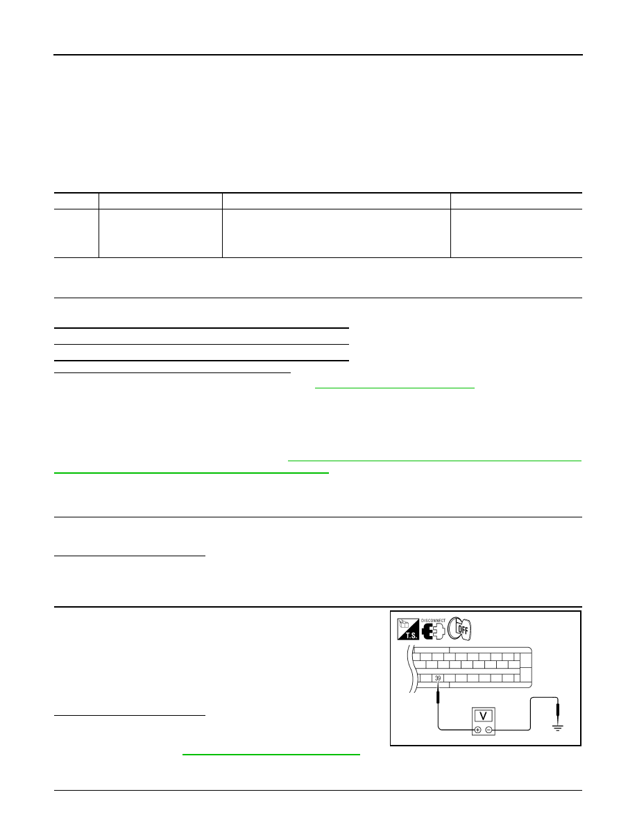
2.

Check the voltage between the ABS actuator and electric unit
(control unit) connector E127 terminal 39 and body ground.

Is the inspection result normal?

YES

>> Perform self-diagnosis again. If the same results

appear, replace ABS actuator and electric unit (control
unit). Refer to 

BRC-300, "Removal and Installation"

.

NO

>> GO TO 3

3.

STOP LAMP SWITCH CIRCUIT INSPECTION

DTC

Display item

Malfunction detected condition

Possible cause

C1116

STOP LAMP SW

When stop lamp switch circuit is open.

• Harness or connector
• Stop lamp switch
• ABS actuator and electric unit 

(control unit)

Self-diagnosis results

STOP LAMP SW

Brake pedal depressed

: Battery voltage 
(approx. 12V)

Brake pedal released

: Approx. 0V

AWFIA0191ZZ

C1116 STOP LAMP SWITCH

BRC-235

< COMPONENT DIAGNOSIS >

[TYPE 3]

C

D

E

G

H

I

J

K

L

M

A

B

BRC

N

O

P

1.

Disconnect the stop lamp switch connector.

2.

Check the continuity between the ABS actuator and electric unit
(control unit) connector E127 (A) terminal 39 and stop lamp
switch connector E39 (B) terminal 2.

Is the inspection result normal?

YES

>> Refer to 

BRC-185, "Work Flow"

.

NO

>> Repair or replace malfunctioning components.

Special Repair Requirement

INFOID:0000000005549798

1.

ADJUSTMENT OF STEERING ANGLE SENSOR NEUTRAL POSITION

Always perform neutral position adjustment for the steering angle sensor when replacing the ABS actuator
and electric unit (control unit). Refer to 

BRC-189, "ADJUSTMENT OF STEERING ANGLE SENSOR NEU-

TRAL POSITION : Description"

.

>> GO TO 2

2.

CALIBRATION OF DECEL G SENSOR

Always perform calibration of decel G sensor when replacing the ABS actuator and electric unit (control unit).
Refer to 

BRC-190, "CALIBRATION OF DECEL G SENSOR : Description"

.

>> END

Continuity should exist.

AWFIA0192ZZ

BRC-236

< COMPONENT DIAGNOSIS >

[TYPE 3]

C1120, C1122, C1124, C1126 IN ABS SOL

C1120, C1122, C1124, C1126 IN ABS SOL

Description

INFOID:0000000005275289

The solenoid valve increases, holds or decreases the fluid pressure of each brake caliper according to the sig-
nals transmitted by the ABS actuator and electric unit (control unit). 

DTC Logic

INFOID:0000000005275290

DTC DETECTION LOGIC

DTC CONFIRMATION PROCEDURE

1.

CHECK SELF-DIAGNOSIS RESULTS

Check the self-diagnosis results.

Is above displayed on the self-diagnosis display?

YES

>> Proceed to diagnosis procedure. Refer to 

BRC-236, "Diagnosis Procedure"

.

NO

>> Inspection End

Diagnosis Procedure

INFOID:0000000005275291

Regarding Wiring Diagram information, refer to 

BRC-275, "Wiring Diagram - BRAKE CONTROL SYSTEM -

WITH HILL DESCENT CONTROL/HILL START ASSIST"

.

1.

CONNECTOR INSPECTION

1.

Turn ignition switch OFF.

2.

Disconnect ABS actuator and electric unit (control unit) connector.

3.

Check terminals for deformation, disconnection, looseness, and so on. If any malfunction is found, repair
or replace terminals.

4.

Reconnect connectors and then perform the self-diagnosis. Refer to 

BRC-212, "CONSULT-III Function

(ABS)"

.

Is any item indicated on the self-diagnosis display?

YES

>> GO TO 2

NO

>> Poor connection of connector terminals. Repair or replace connector.

2.

CHECK SOLENOID, VDC SWITCH-OVER VALVE AND ACTUATOR RELAY POWER SUPPLY CIRCUIT

DTC

Display item

Malfunction detected condition

Possible cause

C1120

FR LH IN ABS SOL

When the control unit detects a malfunction in the front 
LH inlet solenoid circuit.

• ABS actuator and electric unit 

(control unit)

C1122

FR RH IN ABS SOL

When the control unit detects a malfunction in the front 
RH inlet solenoid circuit.

C1124

RR LH IN ABS SOL

When the control unit detects a malfunction in the rear LH 
inlet solenoid circuit.

C1126

RR RH IN ABS SOL

When the control unit detects a malfunction in the rear 
RH inlet solenoid circuit.

Self-diagnosis results

FR LH IN ABS SOL

FR RH IN ABS SOL

RR LH IN ABS SOL

RR RH IN ABS SOL

C1120, C1122, C1124, C1126 IN ABS SOL

BRC-237

< COMPONENT DIAGNOSIS >

[TYPE 3]

C

D

E

G

H

I

J

K

L

M

A

B

BRC

N

O

P

1.

Turn ignition switch OFF.

2.

Disconnect ABS actuator and electric unit (control unit) connec-
tor.

3.

Check voltage between ABS actuator and electric unit (control
unit) connector E127 terminal 32 and ground.

Is the inspection result normal?

YES

>> GO TO 3

NO

>> Repair or replace malfunctioning components.

3.

CHECK SOLENOID, VDC SWITCH-OVER VALVE AND ACTUATOR RELAY GROUND CIRCUIT

Check continuity between ABS actuator and electric unit (control
unit) connector E127 terminals 16, 47 and ground.

Is the inspection result normal?

YES

>> Replace ABS actuator and electric unit (control unit).

Refer to 

BRC-300, "Removal and Installation"

.

NO

>> Repair or replace malfunctioning components.

Component Inspection

INFOID:0000000005275292

1.

CHECK ACTIVE TEST

1.

Select each test menu item on “ACTIVE TEST”.

2.

On the display, touch “Up”, “Keep”, and “Down”, and check that the system operates as shown in the table
below.

*: ON for 1 to 2 seconds after the touch, and then OFF

Is the inspection result normal?

YES

>> Inspection End

NO

>> Go to diagnosis procedure. Refer to 

BRC-236, "Diagnosis Procedure"

.

Special Repair Requirement

INFOID:0000000005549801

1.

ADJUSTMENT OF STEERING ANGLE SENSOR NEUTRAL POSITION

Always perform neutral position adjustment for the steering angle sensor when replacing the ABS actuator
and electric unit (control unit). Refer to 

BRC-189, "ADJUSTMENT OF STEERING ANGLE SENSOR NEU-

TRAL POSITION : Description"

.

ABS actuator and electric unit (control unit)

Voltage

Connector

Terminal

E127

32

Ground

Battery voltage

AWFIA0018ZZ

ABS actuator and electric unit (control unit)

Continuity

Connector

Terminal

E127

16, 47

Ground

Yes

AWFIA0016ZZ

Operation

ABS solenoid valve

Up

Keep

Down

FR RH SOL

FR RH IN SOL

Off

On

On

FR RH OUT SOL

Off

Off

On*

FR LH SOL

FR LH IN SOL

Off

On

On

FR LH OUT SOL

Off

Off

On*

RR RH SOL

RR RH IN SOL

Off

On

On

RR RH OUT SOL

Off

Off

On*

RR LH SOL

RR LH IN SOL

Off

On

On

RR LH OUT SOL

Off

Off

On*


Content   ..  132  133  134  135   ..