Content .. 1166 1167 1168 1169 ..
Nissan Frontier D40. Manual - part 1168
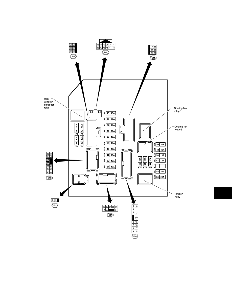
IPDM E/R (INTELLIGENT POWER DISTRIBUTION MODULE ENGINE ROOM)
WW-45
< ECU DIAGNOSIS >
C
D
E
F
G
H
I
J
K
M
A
B
WW
N
O
P
TERMINAL LAYOUT —TYPE B
Physical Values
INFOID:0000000005550192
PHYSICAL VALUES
AAMIA0364GB