Content .. 1145 1146 1147 1148 ..
Nissan Frontier D40. Manual - part 1147
DIAGNOSIS SYSTEM (BCM)
WT-11
< FUNCTION DIAGNOSIS >
C
D
F
G
H
I
J
K
L
M
A
B
WT
N
O
P
DIAGNOSIS SYSTEM (BCM)
CONSULT-III Function (BCM)
INFOID:0000000005275721
CONSULT-III DIAGNOSTIC MODES
CONSULT-III can display each diagnostic item using the diagnostic test modes shown following.
DESCRIPTION
During driving, the tire pressure monitoring system receives the signal transmitted from the transmitter
installed in each wheel, and turns on the low tire pressure warning lamp when the tire pressure becomes low.
The control unit (BCM) for this system has pressure judgement and self-diagnosis functions.
FUNCTION
When the tire pressure monitoring system detects low inflation pressure or an internal malfunction, the low tire
pressure warning lamp in the combination meter comes on. The malfunction is indicated by the low tire pres-
sure warning lamp flashing.
CONSULT-III Application to Tire Pressure Monitoring System
×
: Applicable
– : Not applicable
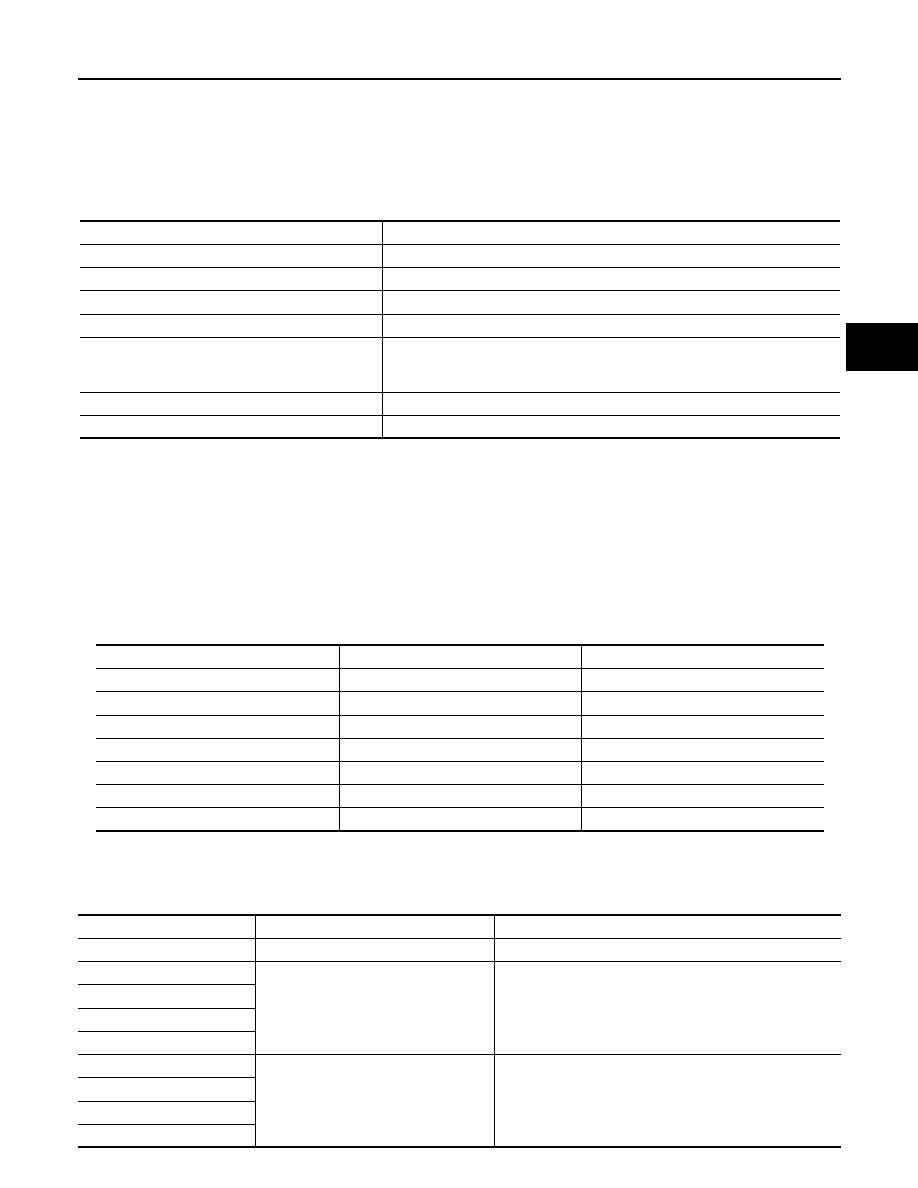
Data Monitor Mode
Diagnostic mode
Description
ECU Identification
BCM part number can be read.
Self Diagnostic Result
Displays BCM self-diagnosis results.
Data Monitor
Displays BCM input/output data in real time.
Active Test
Operation of electrical loads can be checked by sending drive signal to them.
Work support
Supports inspections and adjustments. Commands are transmitted to the BCM
for setting the status suitable for required operation, input/output signals are re-
ceived from the BCM and received data is displayed.
Configuration
Performs BCM configuration read/write functions.
CAN Diag Support Mntr
The result of transmit/receive diagnosis of CAN communication can be read.
ITEM
SELF-DIAGNOSTIC RESULTS
DATA MONITOR
Front - Left transmitter
×
×
Front - Right transmitter
×
×
Rear - Left transmitter
×
×
Rear - Right transmitter
×
×
Warning lamp
—
×
Vehicle speed
×
×
CAN Communication
×
×
MONITOR
CONDITION
SPECIFICATION
VEHICLE SPEED
Drive vehicle.
Vehicle speed (km/h or MPH)
AIR PRESS FL
• Drive vehicle for a few minutes.
or
• Ignition switch ON and activation tool
is transmitting activation signals.
Tire pressure (kPa or psi)
AIR PRESS FR
AIR PRESS RR
AIR PRESS RL
ID REGST FL1
Ignition switch ON
ID not registered: YET
ID registered: DONE
ID REGST FR1
ID REGST RR1
ID REGST RL1