Nissan Frontier D40. Manual - part 1132


  Index      Nissan     Nissan Frontier D40 (2010 year) - Service and Repair Manual


Search            


Content   ..  1130  1131  1132  1133   ..


Nissan Frontier D40. Manual - part 1132


WCS-20

< COMPONENT DIAGNOSIS >

SEAT BELT BUCKLE SWITCH SIGNAL CIRCUIT

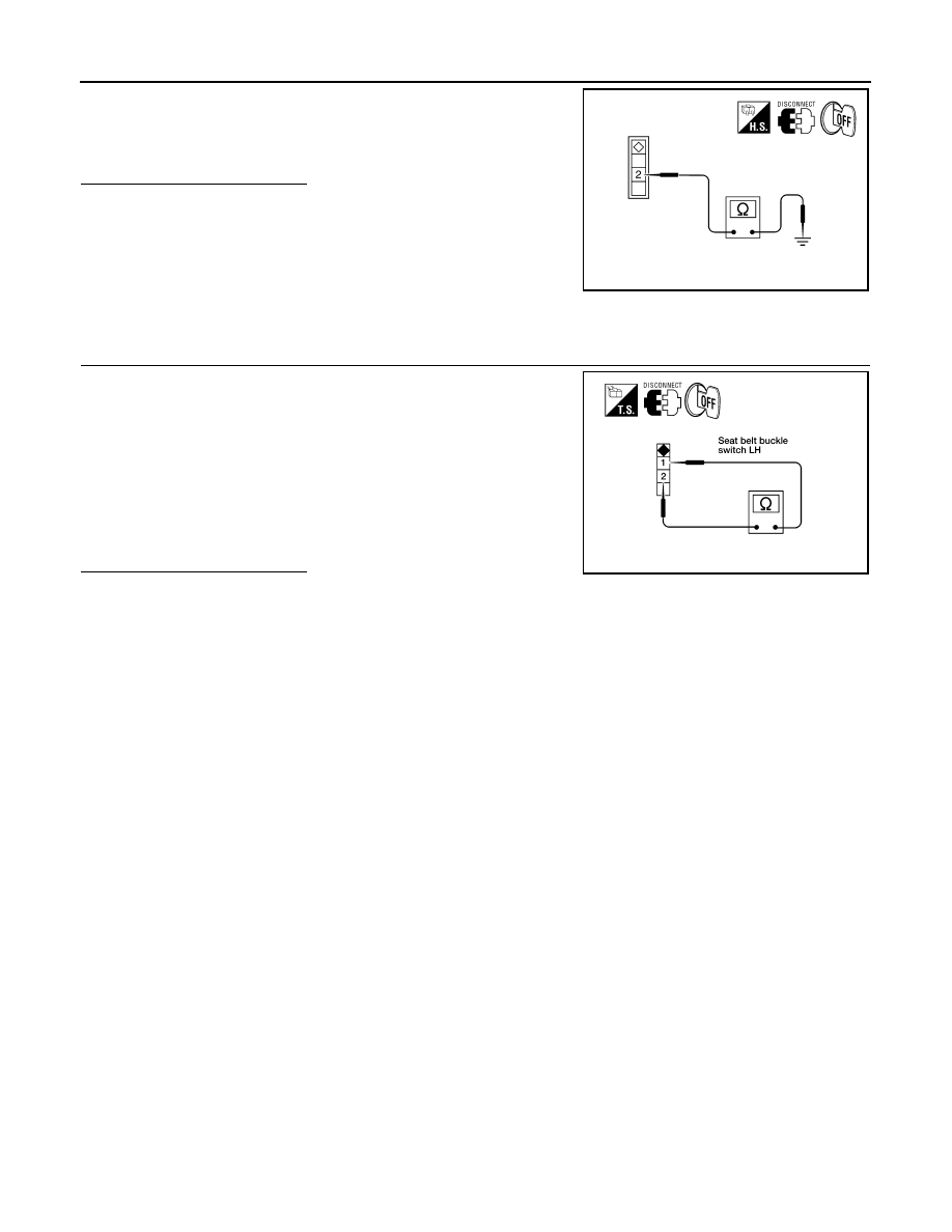
Check continuity between seat belt buckle switch LH harness con-
nector B12 terminal 2 and ground.

Is the inspection result normal?

YES

>> Inspection End.

NO

>> Repair or replace harness.

Component Inspection

INFOID:0000000005274832

1.

 CHECK SEAT BELT BUCKLE SWITCH

1.

Turn ignition switch OFF.

2.

Disconnect the seat belt buckle switch LH connector.

3.

Check continuity between terminals 1 and 2.

Is the inspection result normal?

YES

>> Inspection End.

NO

>> Replace the seat belt buckle switch LH.

2 - Ground

: Continuity should exist.

AWNIA0087ZZ

1– 2

When seat belt is 
fastened

: Continuity should not exist.

When seat belt is 
unfastened

: Continuity should exist.

WKIA1143E

WCS

KEY SWITCH SIGNAL CIRCUIT

WCS-21

< COMPONENT DIAGNOSIS >

C

D

E

F

G

H

I

J

K

L

M

B

A

O

P

KEY SWITCH SIGNAL CIRCUIT

Description

INFOID:0000000005274833

Transmits a key switch signal to the BCM.

Component Function Check

INFOID:0000000005274834

1.

 CHECK BCM INPUT SIGNAL

Select “DATA MONITOR” for “BCM” and check the “KEY ON SW” monitor value.

>> Inspection End.

Diagnosis Procedure

INFOID:0000000005274835

Regarding Wiring Diagram information, refer to 

WCS-23, "Wiring Diagram"

.

1.

 CHECK FUSE

Check if the key switch 10A fuse [No. 25, located in the fuse block (J/B)] is blown.
Is the fuse blown?

YES

>> Replace the blown fuse after repairing the affected circuit.

NO

>> GO TO 2

2.

 CHECK BCM INPUT SIGNAL

Check voltage between BCM harness connector and ground.

Is the inspection result normal?

YES

>> Inspection End.

NO

>> GO TO 3

3.

 CHECK KEY SWITCH CIRCUIT 

1.

Disconnect BCM and key switch.

2.

Check continuity between BCM harness connector M18 (A) and
key switch harness connector M27 (B).

3.

Check continuity between BCM harness connector M18 (A) and
ground.

KEY ON SW

When key is inserted into key cylinder

: ON

When key is removed from key cylinder

: OFF

Terminals

Condition

Voltage

(Approx.)

(+)

(

)

BCM

connector

Terminal

M18

37

Ground

Key is inserted

Battery voltage

Key is removed

0

PKIC0721E

A

B

Continuity

Connector

Terminal

Connector

Terminal

M18

37

M27

1

Yes

WKIA4102E

WCS-22

< COMPONENT DIAGNOSIS >

KEY SWITCH SIGNAL CIRCUIT

Is the inspection result normal?

YES

>> GO TO 4

NO

>> Repair or replace harness.

4.

 CHECK KEY SWITCH POWER SUPPLY CIRCUIT

Check voltage between key switch harness connector and ground.

Is the inspection result normal?

YES

>> Replace key switch.

NO

>> Repair or replace harness.

Component Inspection

INFOID:0000000005274836

1.

 CHECK KEY SWITCH

1.

Turn ignition switch OFF.

2.

Disconnect key switch.

3.

Check continuity between key switch terminals 1 and 2.

Is the inspection result normal?

YES

>> Inspection End.

NO

>> Replace key switch.

A

Ground

Continuity

Connector

Terminal

M18

37

No

Terminals

Voltage

(Approx.)

(+)

(

)

Key switch

Terminal

M27

3

Ground

Battery voltage

WKIA4103E

1 – 2

When key is inserted 
into key cylinder

: Continuity should exist.

When key is removed 
from key cylinder

: Continuity should not exist.

WKIA4101E

WCS

WARNING CHIME SYSTEM

WCS-23

< COMPONENT DIAGNOSIS >

C

D

E

F

G

H

I

J

K

L

M

B

A

O

P

WARNING CHIME SYSTEM

Wiring Diagram

INFOID:0000000005274837

ABNWA0547GB


Content   ..  1130  1131  1132  1133   ..