Nissan Frontier D40. Manual - part 1057


  Index      Nissan     Nissan Frontier D40 (2010 year) - Service and Repair Manual


Search            


Content   ..  1055  1056  1057  1058   ..


Nissan Frontier D40. Manual - part 1057


TM-126

< BASIC INSPECTION >

[5AT: RE5R05A]

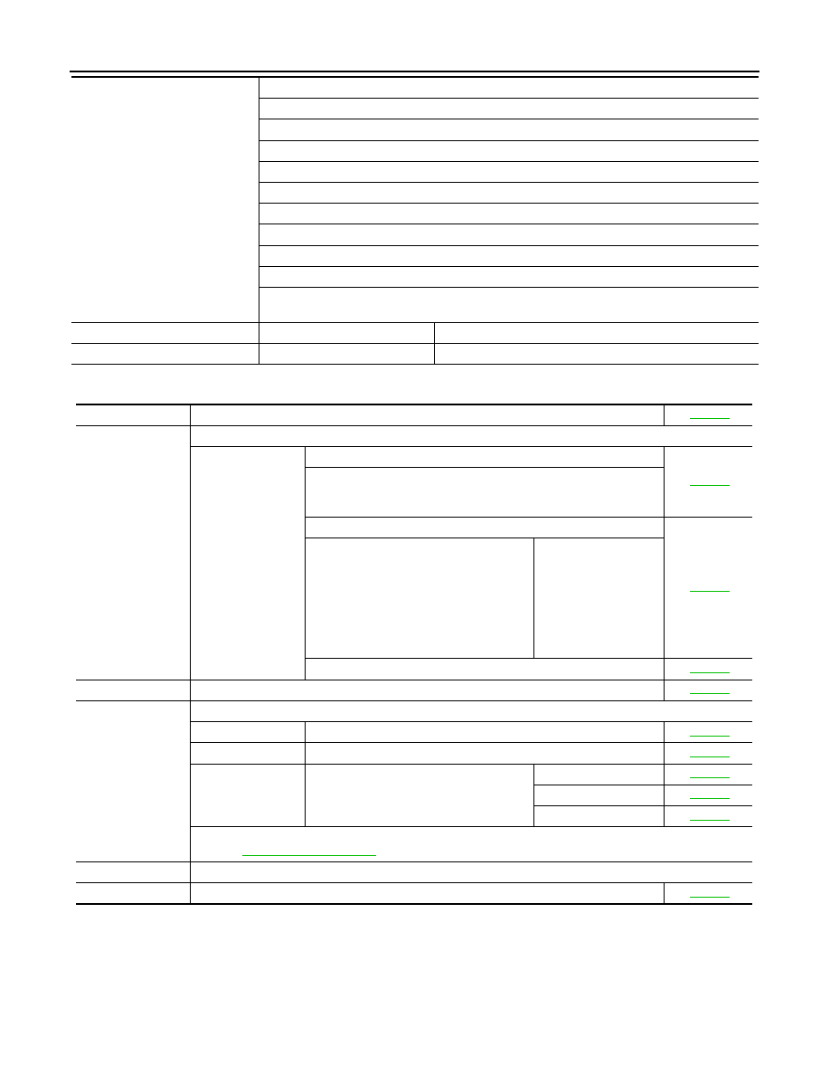
DIAGNOSIS AND REPAIR WORKFLOW

DIAGNOSTIC WORK SHEET

Symptoms

†

 Vehicle does not move.

(

†

 Any position

†

 Particular position)

†

 No up-shift

(

†

 1st 

 2nd

†

 2nd 

 3rd

†

 3rd 

 4th   

†

 4th 

 5th)

†

 No down-shift

(

†

 5th 

 4th   

†

 4th 

 3rd

†

 3rd 

 2nd

†

 2nd 

 1st)

†

 Lock-up malfunction

†

 Shift point too high or too low.

†

 Shift shock or slip

(

†

 N 

 D

†

 N 

 R

†

 Lock-up

†

 Any drive position)

†

 Noise or vibration

†

 No kick down

†

 No pattern select

†

 Cannot be changed to manual mode

†

 Others

(

)

O/D OFF indicator lamp

†

 Continuously lit

†

 Not lit

Malfunction indicator lamp (MIL)

†

 Continuously lit

†

 Not lit

1

†

 Read the item on cautions concerning fail-safe and understand the customer's complaint.

TM-231

2

†

 A/T fluid inspection, stall test and line pressure test

†

 A/T fluid inspection

TM-261

†

 Leak (Repair leak location.)

†

 State

†

 Amount

†

 Stall test

TM-267

†

 Torque converter one-way clutch

†

 Front brake

†

 High and low reverse clutch

†

 Low coast brake

†

 Forward brake

†

 Reverse brake

†

 Forward one-way clutch

†

 1st one-way clutch

†

 3rd one-way clutch

†

 Engine

†

 Line pressure low

†

 Except for input 

clutch and direct clutch, 
clutches and brakes 
OK

†

 Line pressure test - Suspected part:

TM-268

3

†

 Perform self-diagnosis. — Check detected items to repair or replace malfunctioning part.

TM-151

4

†

 Perform road test.

5-1

†

 Check before engine is started

TM-271

5-2

†

 Check at idle

TM-271

5-3

Cruise test

†

 Part 1

TM-272

†

 Part 2

TM-274

†

 Part 3

TM-274

†

 Check malfunction phenomena to repair or replace malfunctioning part after completing all road test.

Refer to 

TM-235, "Symptom Chart"

.

5

†

 Drive vehicle to check that the malfunction phenomenon has been resolved.

6

†

 Erase the results of the self-diagnosis from the TCM and the ECM.

TM-149

A/T CONTROL SYSTEM

TM-127

< FUNCTION DIAGNOSIS >

[5AT: RE5R05A]

C

E

F

G

H

I

J

K

L

M

A

B

TM

N

O

P

FUNCTION DIAGNOSIS

A/T CONTROL SYSTEM

Cross-Sectional View

INFOID:0000000005273978

2WD models

SCIA5267E

1.

Front planetary gear

2.

Mid planetary gear

3.

Rear planetary gear

4.

Direct clutch

5.

High and low reverse clutch

6.

Reverse brake

7.

Drum support

8.

Forward brake

9.

Low coast brake

10. Input shaft

11.

Torque converter

12. Oil pump

13. Front brake

14.

3rd one-way clutch

15. Input clutch

16. 1st one-way clutch

17.

Control valve with TCM

18. Forward one-way clutch

19. Rear extension

20.

Output shaft

TM-128

< FUNCTION DIAGNOSIS >

[5AT: RE5R05A]

A/T CONTROL SYSTEM

4WD models

Shift Mechanism

INFOID:0000000005273979

The automatic transmission uses compact triple planetary gear systems to improve power-transmission effi-
ciency, simplify construction and reduce weight.
It also employs an optimum shift control and super wide gear ratios. They improve starting performance and
acceleration during medium and high-speed operation.

CONSTRUCTION 

SCIA5268E

1.

Front planetary gear

2.

Mid planetary gear

3.

Rear planetary gear

4.

Direct clutch

5.

High and low reverse clutch

6.

Reverse brake

7.

Drum support

8.

Forward brake

9.

Low coast brake

10. Input shaft

11.

Torque converter

12. Oil pump

13. Front brake

14.

3rd one-way clutch

15. Input clutch

16. 1st one-way clutch

17.

Control valve with TCM

18. Forward one-way clutch

19. Adapter case

20.

Output shaft

A/T CONTROL SYSTEM

TM-129

< FUNCTION DIAGNOSIS >

[5AT: RE5R05A]

C

E

F

G

H

I

J

K

L

M

A

B

TM

N

O

P

FUNCTION OF CLUTCH AND BRAKE 

CLUTCH AND BAND CHART 

1.

Front brake

 2.

Input clutch

3.

Direct clutch

4.

High and low reverse clutch

5.

Reverse brake

6.

Forward brake

7.

Low coast brake

8.

1st one-way clutch

9.

Forward one-way clutch

10. 3rd one-way clutch

11.

Front sun gear

12. Input shaft

13. Mid internal gear

14.

Front internal gear

15. Rear carrier

16. Rear sun gear

17.

Mid sun gear

18. Front carrier

19. Mid carrier

20.

Rear internal gear

21. Output shaft

22. Parking gear

23.

Parking pawl

PCIA0002J

Name of the Part

Abbreviation

 Function

Front brake (1)

FR/B

Fastens the front sun gear (11).

Input clutch (2)

I/C

Connects the input shaft (12), the front internal gear (14) and the mid internal 
gear (13).

Direct clutch (3)

D/C

Connects the rear carrier (15) and the rear sun gear (16).

High and low reverse clutch (4)

HLR/C

Connects the mid sun gear (17) and the rear sun gear (16).

Reverse brake (5)

R/B

Fastens the rear carrier (15).

Forward brake (6)

Fwd/B

Fastens the mid sun gear (17).

Low coast brake (7) 

LC/B

Fastens the mid sun gear (17).

1st one-way clutch (8)

1st WOC

Allows the rear sun gear (16) to turn freely forward relative to the mid sun gear 
(17) but fastens it for reverse rotation.

Forward one-way clutch (9)

Fwd OWC

Allows the mid sun gear (17) to turn freely in the forward direction but fastens it 
for reverse rotation.

3rd one-way clutch (10)

3rd OWC

Allows the front sun gear (11) to turn freely in the forward direction but fastens 
it for reverse rotation.

Shift position

I/C

HLR/C

D/C

R/B

FR/B

LC/B 

Fwd/B

1st 

OWC

Fwd 

OWC

3rd 

OWC

Remarks

P

PARK POSITION

R

REVERSE POSI-

TION


Content   ..  1055  1056  1057  1058   ..