Nissan Frontier D40. Manual - part 84


  Index      Nissan     Nissan Frontier D40 (2010 year) - Service and Repair Manual


Search            


Content   ..  82  83  84  85   ..


Nissan Frontier D40. Manual - part 84


BRC-34

< COMPONENT DIAGNOSIS >

[TYPE 1]

C1111 ABS MOTOR, MOTOR RELAY SYSTEM

C1111 ABS MOTOR, MOTOR RELAY SYSTEM

Description

INFOID:0000000005275062

PUMP

The pump returns the brake fluid stored in the reservoir to the master cylinder by reducing the pressure. 

MOTOR

The motor drives the pump according to the signals transmitted by the ABS actuator and electric unit (control
unit). 

DTC Logic

INFOID:0000000005275063

DTC DETECTION LOGIC

DTC CONFIRMATION PROCEDURE

1.

CHECK SELF-DIAGNOSIS RESULTS

Check the self-diagnosis results.

Is above displayed on the self-diagnosis display?

YES

>> Proceed to diagnosis procedure. Refer to 

BRC-34, "Diagnosis Procedure"

.

NO

>> Inspection End

Diagnosis Procedure

INFOID:0000000005275064

Regarding Wiring Diagram information, refer to 

BRC-51, "Wiring Diagram - BRAKE CONTROL SYSTEM -

ABS"

.

1.

CONNECTOR INSPECTION

1.

Turn ignition switch OFF.

2.

Disconnect ABS actuator and electric unit (control unit) connector.

3.

Check terminals for deformation, disconnect, looseness, and so on. If any malfunction is found, repair or
replace terminals.

4.

Reconnect connectors and then perform the self-diagnosis. Refer to 

BRC-21, "CONSULT-III Function

(ABS)"

.

Is any item indicated on the self-diagnosis display?

YES

>> GO TO 2

NO

>> Poor connection of connector terminals. Repair or replace connector.

2.

CHECK ABS MOTOR AND MOTOR RELAY POWER SUPPLY CIRCUIT
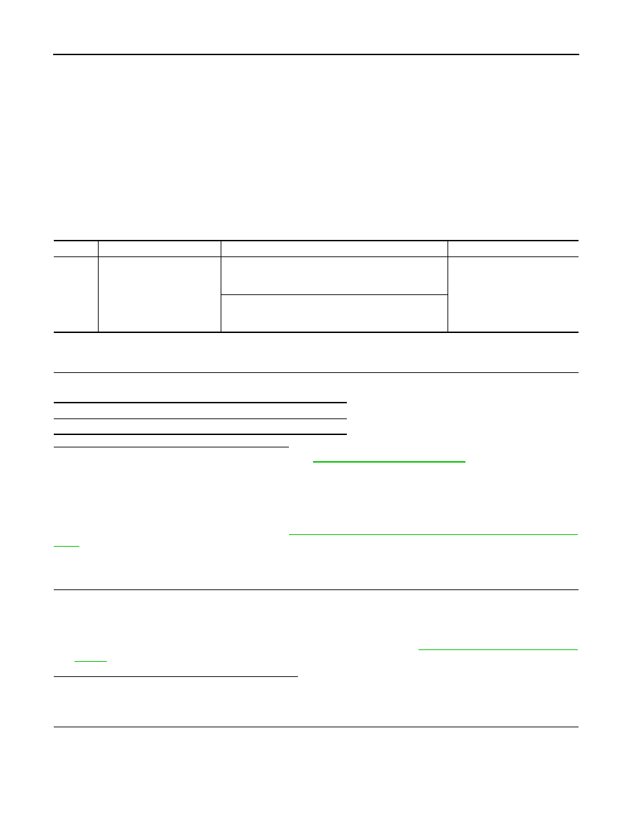
DTC

Display item

Malfunction detected condition

Possible cause

C1111

PUMP MOTOR

During the actuator motor operating with ON, when the 
actuator motor turns OFF, or when the control line for ac-
tuator motor relay is open.

• Harness or connector
• ABS actuator and electric unit 

(control unit)

During the actuator motor operating with OFF, when the 
actuator motor turns ON, or when the control line for relay 
is shorted to ground.

Self-diagnosis results

PUMP MOTOR

C1111 ABS MOTOR, MOTOR RELAY SYSTEM

BRC-35

< COMPONENT DIAGNOSIS >

[TYPE 1]

C

D

E

G

H

I

J

K

L

M

A

B

BRC

N

O

P

1.

Turn ignition switch OFF.

2.

Disconnect ABS actuator and electric unit (control unit) connec-
tor.

3.

Check voltage between the ABS actuator and electric unit (con-
trol unit) connector E125 terminal 1 and ground.

Is the inspection result normal?

YES

>> GO TO 3

NO

>> Repair or replace malfunctioning components.

3.

CHECK ABS ACTUATOR AND ELECTRIC UNIT (CONTROL UNIT) GROUND CIRCUIT

Check continuity between ABS actuator and electric unit (control
unit) connector E125 terminals 16, 47 and ground.

Is the inspection result normal?

YES

>> Replace ABS actuator and electric unit (control unit).

Refer to 

BRC-71, "Removal and Installation"

.

NO

>> Repair or replace malfunctioning components.

Component Inspection

INFOID:0000000005275065

1.

CHECK ACTIVE TEST

1.

On “ACTIVE TEST”, select “ABS MOTOR”.

2.

Touch On and Off on screen. Make sure motor relay and actuator relay operate as shown in table below.

Is the inspection result normal?

YES

>> Inspection End

NO

>> Go to diagnosis procedure. Refer to 

BRC-34, "Diagnosis Procedure"

.

ABS actuator and electric unit (control unit)

Voltage

Connector

Terminal

E125

1

Ground

Battery voltage

AWFIA0017ZZ

ABS actuator and electric unit (control unit)

Continuity

Connector

Terminal

E125

16, 47

Ground

Yes

AWFIA0016ZZ

Operation

On

Off

MOTOR RELAY

On

Off

ACTUATOR RLY

On

On

BRC-36

< COMPONENT DIAGNOSIS >

[TYPE 1]

C1115 WHEEL SENSOR

C1115 WHEEL SENSOR

Description

INFOID:0000000005275066

When the sensor rotor rotates, the magnetic field changes. It converts the magnetic field changes to current
signals (rectangular wave) and transmits them to the ABS actuator and electric unit (control unit). 

DTC Logic

INFOID:0000000005275067

DTC DETECTION LOGIC

DTC CONFIRMATION PROCEDURE

1.

CHECK SELF-DIAGNOSIS RESULTS

Check the self-diagnosis results.

Is above displayed on the self-diagnosis display?

YES

>> Proceed to diagnosis procedure. Refer to 

BRC-36, "Diagnosis Procedure"

.

NO

>> Inspection End

Diagnosis Procedure

INFOID:0000000005549003

Regarding Wiring Diagram information, refer to 

BRC-51, "Wiring Diagram - BRAKE CONTROL SYSTEM -

ABS"

.

CAUTION:

Do not check between wheel sensor terminals.

1.

CONNECTOR INSPECTION

1.

Disconnect the ABS actuator and electric unit (control unit) connector and wheel sensor of malfunctioning
code. 

2.

Check the terminals for deformation, disconnection, looseness or damage.

Is the inspection result normal?

YES

>> GO TO 2

NO

>> Repair or replace as necessary.

2.

CHECK WHEEL SENSOR OUTPUT SIGNAL

1.

Connect ABS active wheel sensor tester (J-45741) to wheel sensor using appropriate adapter.

2.

Turn on the ABS active wheel sensor tester power switch.
NOTE:
The green POWER indicator should illuminate. If the POWER indicator does not illuminate, replace the
battery in the ABS active wheel sensor tester before proceeding.

3.

Spin the wheel of the vehicle by hand and observe the red SENSOR indicator on the ABS active wheel
sensor tester. The red SENSOR indicator should flash on and off to indicate an output signal.
NOTE:
If the red SENSOR indicator illuminates but does not flash, reverse the polarity of the tester leads and
retest.

Does the ABS active wheel sensor tester detect a signal?

YES

>> GO TO 3

DTC

Display item

Malfunction detected condition

Possible cause

C1115

ABS SENSOR
[ABNORMAL SIGNAL]

When wheel sensor input signal is malfunctioning.

• Harness or connector
• Wheel sensor
• ABS actuator and electric unit 

(control unit)

Self-diagnosis results

ABS SENSOR [ABNORMAL SIGNAL]

C1115 WHEEL SENSOR

BRC-37

< COMPONENT DIAGNOSIS >

[TYPE 1]

C

D

E

G

H

I

J

K

L

M

A

B

BRC

N

O

P

NO

>> Replace the wheel sensor. Refer to 

BRC-69, "Removal and Installation"

.

3.

CHECK TIRES

Check the inflation pressure, wear and size of each tire.

Is the inspection result normal?

YES

>> GO TO 4

NO

>> Adjust tire pressure or replace tire(s).

4.

CHECK WHEEL BEARINGS

Check wheel bearing axial end play. Refer to 

FAX-5, "On-Vehicle Inspection and Service"

 (front) or 

RAX-6,

"Rear Axle Bearing"

 (rear).

Is the inspection result normal?

YES

>> GO TO 5

NO

>> Repair or replace as necessary. Refer to 

FAX-8, "Removal and Installation"

 (front) or 

RAX-12,

"Removal and Installation"

 (rear).

5.

CHECK WIRING HARNESS FOR SHORT CIRCUIT

1.

Disconnect ABS actuator and electric unit (control unit) connec-
tor and wheel sensor connector of malfunction code No.

2.

Check continuity between wheel sensor connector terminals
and ground.

Is the inspection result normal?

YES

>> GO TO 6

NO

>> Repair the circuit.

6.

CHECK WIRING HARNESS FOR OPEN CIRCUIT

1.

Check continuity between ABS actuator and electric unit (control unit) connector and the malfunctioning
wheel sensor connector.

Is the inspection result normal?

YES

>> Replace the ABS actuator and electric unit (control unit). Refer to 

BRC-71, "Removal and Installa-

tion"

.

NO

>> Repair the circuit.

Component Inspection

INFOID:0000000005549004

1.

CHECK DATA MONITOR

On “DATA MONITOR”, select “FR LH SENSOR”, “FR RH SENSOR”, “RR LH SENSOR”, and “RR RH SEN-
SOR”, and check the vehicle speed.

Continuity should not exist.

AWFIA0188ZZ

Wheel sensor

ABS actuator and 

electric unit (control unit)

Wheel sensor

Continuity

Connector

Terminal

Connector

Terminal

Front LH

E125

45

E18

1

Yes

46

2

Front RH

34

E117

1

33

2

Rear LH

36

C11

1

37

2

Rear RH

43

C10

1

42

2


Content   ..  82  83  84  85   ..