Nissan Terrano model r20 series 2004. Manual - part 424


  Index      Nissan     Nissan Terrano model r20 series 2004 - Service and Repair Manual


Search            


Content   ..  422  423  424  425   ..


Nissan Terrano model r20 series 2004. Manual - part 424


DIAGNOSTIC PROCEDURE 6
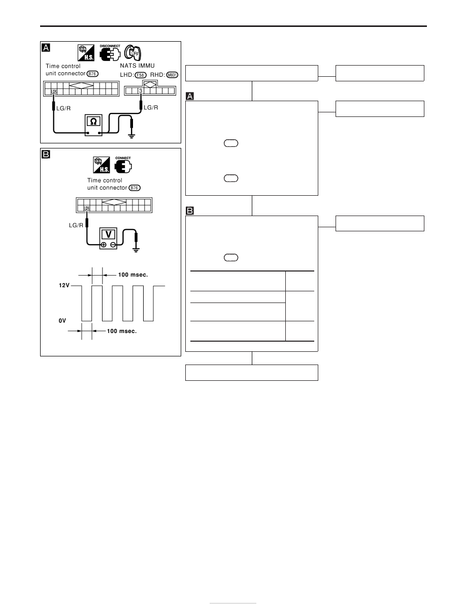
(NATS release signal check)

Does engine start properly?

Yes

E

No

Check NATS system.

CHECK NATS SIGNAL CIRCUIT.
1) Disconnect control unit connector and

NATS IMMU connector.

2) Check continuity between control unit

terminal

U26

and NATS IMMU termi-

nal

q

3

.

Continuity should exist.

3) Check continuity between control unit

terminal

U26

and ground.

Continuity should not exist.

OK

E

NG

Repair harness.

CHECK NATS RELEASE SIGNAL.
1) Connect control unit connector and

NATS IMMU connector.

2) Check voltage between control unit

terminal

U26

and ground.

OK

E

NG

Check NATS system.

Replace time control unit.

Ignition switch condition

Voltage

(V)

LOCK

12

More than 10 seconds after ignition

switch turned to “ON” position

For 10 seconds after ignition

switch turned to “ON” position

Pulse

YEL314D

YEL315D

H

H

H

POWER DOOR LOCK — SUPER LOCK —

Trouble Diagnoses (Cont’d)

EL-200

DIAGNOSTIC PROCEDURE 7
(Ignition switch check)

CHECK IGNITION SWITCH INPUT SIG-
NAL.
Check voltage between control unit termi-
nal

U22

and ground.

NG

E

OK

Ignition switch is OK.

CHECK IGNITION SWITCH POWER
SUPPLY.
Check voltage between ignition switch
harness terminal

q

2

and ground.

Battery voltage should exist.

OK

E

NG

Check the following.

I

10A fuse [No. 16 ,
located in fuse block
(J/B)]

I

Harness for open or
short between ignition
switch and fuse

CHECK IGNITION SWITCH.
1. Disconnect ignition switch connector.
2. Check continuity between ignition

switch terminals.

OK

E

NG

Replace ignition switch.

Check harness for open or short between
control unit and ignition switch.

Condition of key switch

Voltage (V)

Key is inserted

Approx. 12

Key withdrawn

0

Terminals

Condition

Continuity

q

1

-

q

2

Key is

inserted.

Yes

Key is with-

drawn.

No

DIAGNOSTIC PROCEDURE 8
(Ignition switch “ON” circuit check)

Terminals

Ignition switch position

!

@

OFF

ACC

ON

U01

Ground

0V

0V

Battery voltage

If NG, check the following.

I

10A fuse [No.

26

, located in the fuse block (J/B)]

I

Harness for open or short

YEL316D

YEL317D

YEL914E

YEL319D

H

H

H

POWER DOOR LOCK — SUPER LOCK —

Trouble Diagnoses (Cont’d)

EL-201

System Description

POWER AND GROUND

Power is supplied at all times

I

to time control unit terminal U09 and

I

to door lock switch relay terminal 1

I

through 10A fuse [No. 5, located in the fuse block (J/B)], and

I

to key switch terminal 2

I

through 10A fuse [No. 16, located in the fuse block (J/B)].

When the key switch is ON (ignition key is inserted in key cylinder), power is supplied

I

through key switch terminal 1

I

to time control unit terminal U22.

When the door switch driver side is ON (door is OPEN), ground is supplied

I

to time control unit terminal U06

I

through door switch driver side terminal 1 and case ground.

When any of the other door switches is ON (door is OPEN), ground is supplied

I

to time control unit terminal U07

I

through door switch terminal 1 and case ground.

When lock/unlock switch is LOCK, ground is supplied

I

to power window main switch terminal 3

I

through body grounds B10 and B18.

Door lock operation signal is supplied

I

through power window main switch terminal 14

I

to door lock switch relay terminal 2.

With power and ground supplied, door lock switch relay is energized, and the door lock operation signal is
supplied to time control unit terminal U35.
Door unlock operation signal is supplied

I

through power window main switch terminal 7

I

to time control unit terminal U37.

Remote controller signal is inputted to time control unit (The antenna of the system is combined with time
control unit).

FUNCTION

Multi-remote control system has the following function.

I

Door lock (and set super lock)

I

Door unlock (and release super lock)

I

Hazard reminder

LOCK OPERATION

To lock door by multi-remote controller, the key switch must be at OFF.
When the LOCK signal is input to time control unit (the antenna of the system is combined with time control
unit), time control unit controls to lock doors and set super lock (models with super lock).

UNLOCK OPERATION

Normal Mode

When UNLOCK signal is input to time control unit (the antenna of the system is combined with time control
unit), time control unit controls to unlock doors and release super lock (models with super lock).

Anti Hi-jack Mode

When the UNLOCK signal is input to time control unit (the antenna of the system is combined with time con-
trol unit), time control unit controls to unlock driver’s door and release super lock (models with super lock).
Then, if an unlock signal is sent from the remote controller again within 5 seconds, all other doors will be
unlocked.

HAZARD REMINDER

When the doors are locked or unlocked by multi-remote controller, supply power to turn lamps hazard reminder
flashes as follows

I

Lock operation: Flash once

I

Unlock operation: Flash twice

MULTI-REMOTE CONTROL SYSTEM

EL-202

AUTO DOOR LOCK OPERATION

Auto lock function signal is sent for operation when any of the following signals are not sent within 5 minutes
after the unlock signal is sent from the multi-remote controller:

I

when door switch is turned ON for open

I

when the ignition switch is turned ON

I

when the lock signal is sent from the multi-remote controller

I

when ignition switch is inserted in ignition key cylinder

MULTI-REMOTE CONTROLLER ID CODE ENTRY

A maximum of four remote controllers can be entered.
To enter ID code entry, the following signals must be input to the time control unit.

I

Ignition switch (ON)

I

Signal from remote controller

For detailed procedure, refer to “ID Code Entry Procedure” in EL-215.

MULTI-REMOTE CONTROL SYSTEM

System Description (Cont’d)

EL-203


Content   ..  422  423  424  425   ..