Index Nissan Nissan Terrano model r20 series 2004 - Service and Repair Manual
Search
Content .. 395 396 397 398 ..
Nissan Terrano model r20 series 2004. Manual - part 397
Trouble Diagnoses
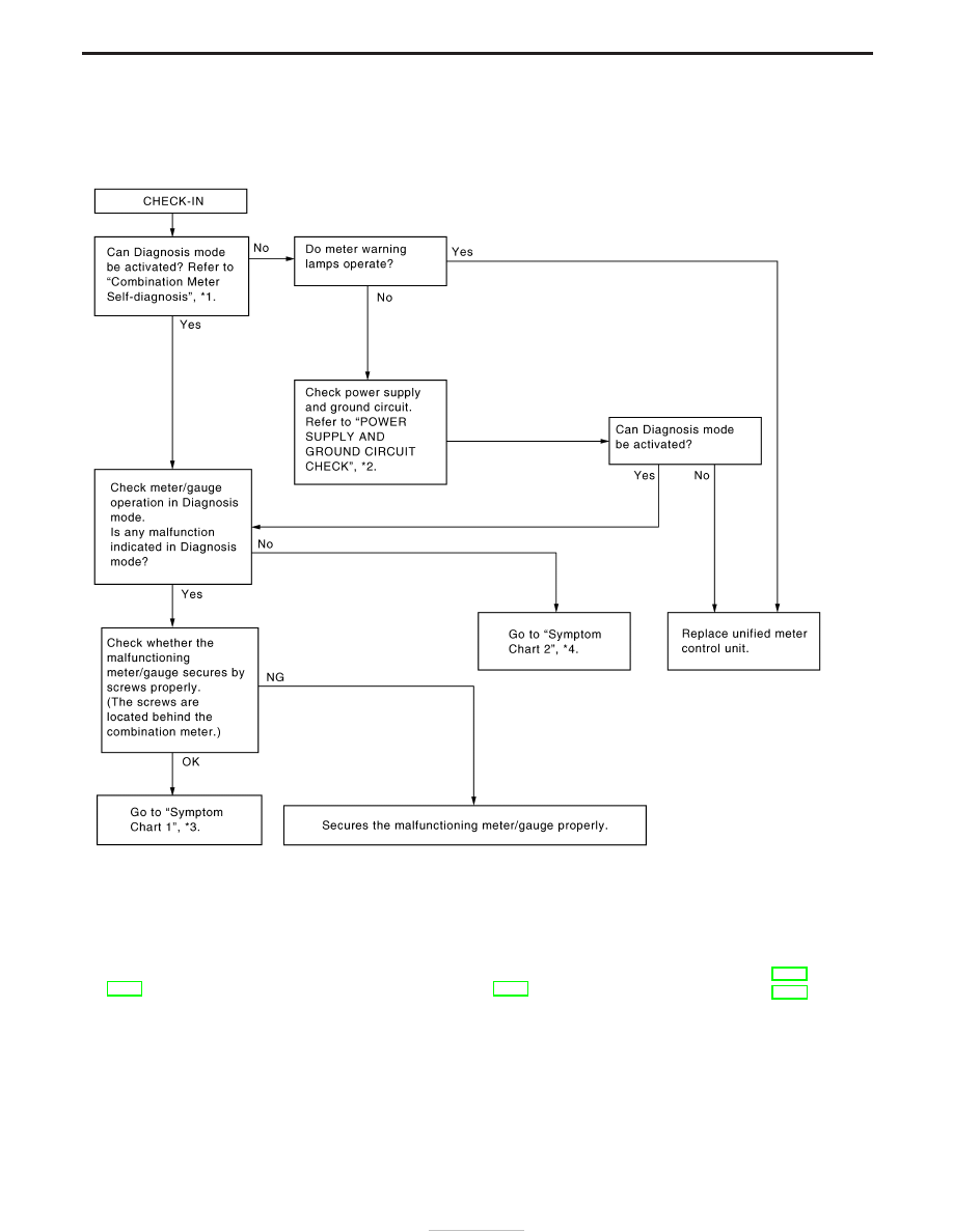
PRELIMINARY CHECK
*1: Combination Meter Self-Diagnosis
(EL-90)
*2: POWER SUPPLY AND GROUND
CIRCUIT CHECK (EL-83)
*3: Symptom Chart 1 (EL-93)*4: Symptom Chart 2 (EL-93
)
SEL361WB
METER AND GAUGES
EL-92