Nissan Terrano model r20 series 2004. Manual - part 296


  Index      Nissan     Nissan Terrano model r20 series 2004 - Service and Repair Manual


Search            


Content   ..  294  295  296  297   ..


Nissan Terrano model r20 series 2004. Manual - part 296


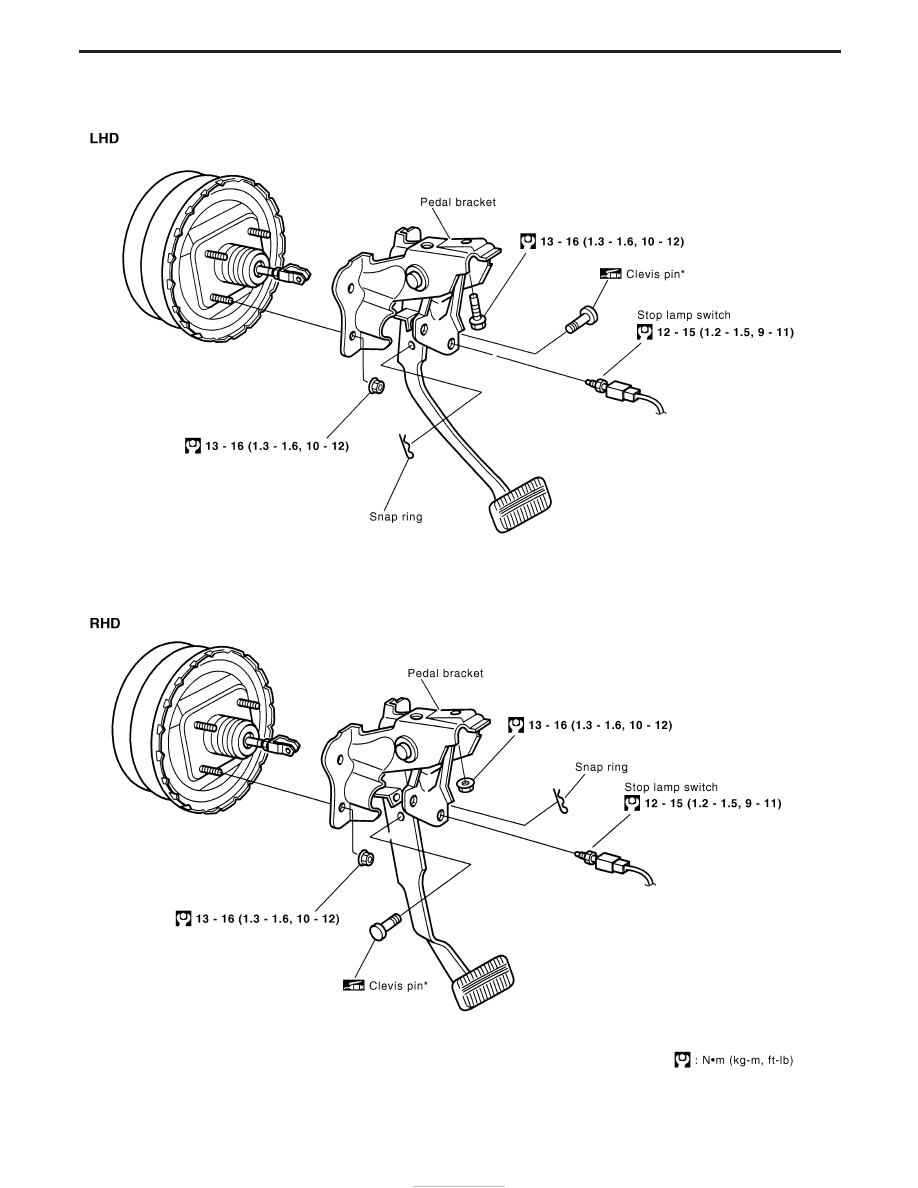
Removal and Installation

YBR446

BRAKE PEDAL AND BRACKET

BR-14

Removal

1. Remove stop lamp switch connector and stop lamp switch.
2. Remove bolt for (LHD) or nut for (RHD) securing pedal bracket

to the front panel.

3. Remove snap ring and pull clevis pin from the brake pedal.
4. Remove 4 mounting nuts securing pedal bracket to the brake

booster.

Installation

Install pedal bracket in the reverse order of the removal.
NOTE:
Pay attention to the direction of the clevis pin for installation.

Inspection

Check brake pedal for following items:

I

Brake pedal bend

I

Clevis pin deformation

I

Crack of any welded portion

I

Crack or deformation of clevis pin stopper

SBR997

BRAKE PEDAL AND BRACKET

BR-15

Adjustment

Check brake pedal free height from dash reinforcement panel.

H: Free height

Refer to SDS, BR-86.

D: Full stroke

Refer to SDS, BR-86.

C: Clearance between pedal stopper and threaded end

of stop lamp switch

0.3 - 1.0 mm (0.012 - 0.039 in)

A: Pedal free play

1.0 - 3.0 mm (0.039 - 0.118 in)

If necessary, adjust brake pedal free height.
1. Loosen lock nut and adjust pedal free height by turning brake

booster input rod. Then tighten lock nut.

Make sure that tip of input rod stays inside of clevis as shown.
2. Loosen lock nut and adjust clearance “C” with stop lamp switch.

Then tighten lock nuts.

3. Check pedal free play.
Make sure that stop lamps go off when pedal is released.
4. Check brake system for leaks, accumulation of air or any dam-

age to components (master cylinder, etc.); then make neces-
sary repairs.

5. After installation and adjustment, operate the brake pedal to full

stroke several times to confirm that strange sound interference
hitching or other do not arise working smoothly throughout the
stroke.

YBR450

YBR300

BRAKE PEDAL AND BRACKET

BR-16

Removal

CAUTION:

Be careful not to splash brake fluid on painted areas; it may
cause paint damage. If brake fluid is splashed on painted
areas, wash it away with water immediately. DO NOT RUB.
1. Connect a vinyl tube to air bleeder valve.
2. Drain brake fluid from each air bleeder valve, depressing brake

pedal to empty fluid from master cylinder.

3. Remove brake pipe flare nuts.
4. Remove master cylinder mounting nuts.
5. Remove protector of master cylinder, and avoid scratching the

surface of master cylinder during removal.

CAUTION:

Do not disassemble master cylinder.
NOTE:
If it is necessary to change the brake fluid reservoir, remove it
as shown in the illustration on the left, while holding the seals
with one hand.
It is not necessary to replace the seals if they are in a good
condition.

Installation

CAUTION:

I

Refill with new brake fluid “DOT 4”.

I

Never reuse drained brake fluid.

1. Place master cylinder onto brake booster and secure mounting

nuts lightly.

2. Fit flare nuts to master cylinder.
3. Tighten mounting nuts.

: 21 - 29 N

m (2.1 - 3.0 kg-m, 15 - 22 ft-lb)

4. Tighten flare nuts.

: 15 - 18 N

m (1.5 - 1.8 kg-m, 11 - 13 ft-lb)

5. Bleed air. Refer to “Bleeding Brake System”, “BRAKE

HYDRAULIC LINE”, BR-8.

YBR258

EBR080

MASTER CYLINDER

BR-17


Content   ..  294  295  296  297   ..