Nissan Terrano model r20 series 2004. Manual - part 288
General Specifications
TORSION BAR SPRING
Applied model
Hardtop
Wagon
Spring diameter x length
mm (in)
26.0 x 1,230 (1.024 x 48.43)
Spring constant
N/mm (kg/mm, lb/in)
25.3 (2.58, 144.5)
SHOCK ABSORBER
Applied model
ABS models
Shock absorber type
Non-adjustable (hydraulic)
Damping force
N (kg, lb)
[at 0.3 m (1.0 ft)/sec.]
Extension
2,265±314
(231.0±32.0,
509.2±70.6)
Compression
653±124
(66.6±12.6,
146.8±27.9)
STABILIZER BAR
Applied model
All
Stabilizer bar diameter
mm (in)
29 (1.14)
COMPRESSION ROD
Applied model
Hardtop
Wagon
Rod diameter
mm (in)
23.5 (0.925)
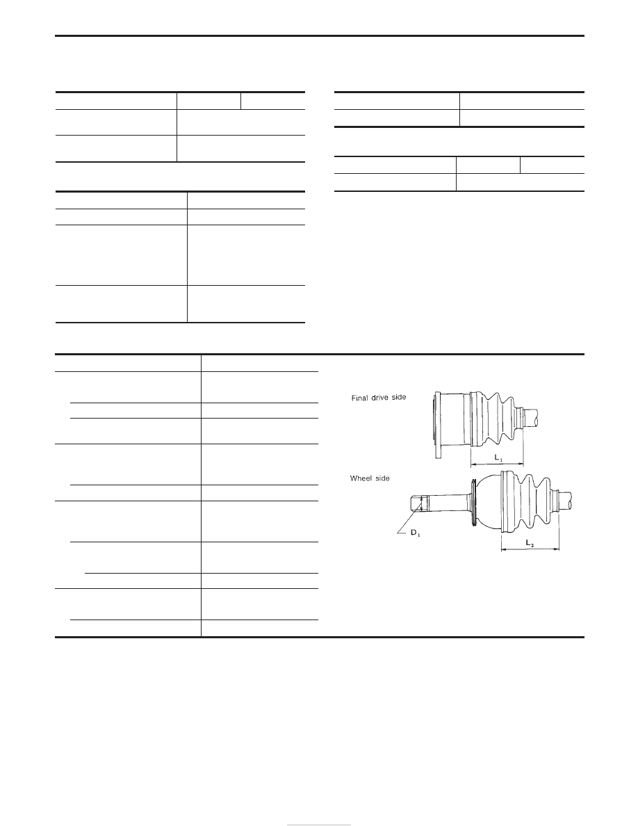
DRIVE SHAFT
Applied model
All
SFA877A
Drive shaft joint type
Final drive side
TS82F
Wheel side
ZF100
Fixed joint axial end play
limit
mm (in)
1.0 (0.039)
Wheel side
Pitch circle diameter serration
mm (in)
27.0 (1.063)
Major diameter (D1)
mm (in)
28.0 (1.102)
Grease
Quality
Nissan genuine grease or
equivalent
Capacity
g (oz)
Final drive side
190 - 210 (6.70 - 7.41)
Wheel side
100 - 120 (3.53 - 4.23)
Boot length
mm (in)
Final drive side (L
1
)
97 - 99 (3.82 - 3.90)
Wheel side (L
2
)
96 - 98 (3.78 - 3.86)
SERVICE DATA AND SPECIFICATIONS (SDS)
FA-38