Nissan Terrano model r20 series 2004. Manual - part 165
Diagnostic Procedure
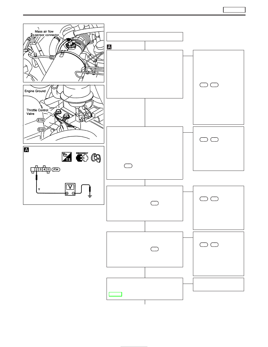
INSPECTION START
CHECK POWER SUPPLY.
1. Turn ignition switch to “LOCK” position.
2. Disconnect mass air flow sensor har-
ness connector.
3. Turn ignition switch to “ON” position.
4. Check voltage between mass air flow
sensor connector terminal
q
2
and
engine ground with CONSULT-II or
tester.
Voltage: Battery positive voltage
OK
E
NG
Check the following:
I
10A fuse
I
Harness continuity
between ECM relay (coil
and load side) connector
and battery supply
I
Harness connectors
F100
,
M775
(RHD mod-
els)
I
Harness continuity
between ECM relay con-
nector and Mass Air
Flow Sensor Connector.
If NG, replace 10A fuse or
repair or replace harness
or connectors.
CHECK GROUND CIRCUIT.
1. Turn ignition switch to “LOCK” position.
2. Disconnect ECM harness connector.
3. Loosen and retighten engine ground
screws.
4. Check harness continuity between
mass air flow sensor harness connec-
tor terminal
q
3
and ECM connector ter-
minal
218
. Refer to wiring diagram.
Continuity should exist.
If OK, check harness for short-circuit.
OK
E
NG
Check the following.
I
Harness connectors
F100
,
M775
(RHD mod-
els)
I
Harness continuity
between mass air flow
sensor and ECM
If NG, repair or replace
harness or connectors.
CHECK INPUT SIGNAL CIRCUIT.
Check harness continuity between mass
air flow sensor connector terminal
q
4
and
ECM connector terminal
223
. Refer to
wiring diagram.
Continuity should exist.
If OK, check harness for short-circuit.
OK
E
NG
Check the following.
I
Harness connectors
F100
,
M775
(RHD mod-
els)
I
Harness continuity
between mass air flow
sensor and ECM
If NG, repair or replace
harness or connectors.
CHECK INPUT SIGNAL CIRCUIT.
Check harness continuity between mass
air flow sensor connector terminal
q
5
and
ECM connector terminal
224
. Refer to
wiring diagram.
Continuity should exist.
If OK, check harness for short-circuit.
OK
E
NG
Check the following.
I
Harness connectors
F100
,
M775
(RHD mod-
els)
I
Harness continuity
between mass air flow
sensor and ECM
If NG, repair or replace
harness or connectors.
CHECK COMPONENT
(Mass air flow sensor).
Refer to “COMPONENT INSPECTION”,
EC-383.
OK
E
NG
Replace mass air flow sen-
sor.
q
A
NEF664
NEF591
NEF352
H
H
H
H
H
H
DTC P0100 MASS AIR FLOW SEN
TD27Ti
EC-382