Nissan Terrano r20e. Manual - part 418


  Index      Nissan     Nissan Terrano r20e - Service and Repair Manual


Search            


Content   ..  416  417  418  419   ..


Nissan Terrano r20e. Manual - part 418


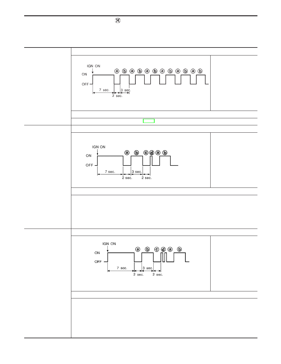
Air Bag Warning Lamp Flash Code Chart (Diagnosis
mode)

I

Diagnosis results (pre-
viously stored in the
memory) might not be
erased after repair.

I

Intermittent malfunction
has been detected in
the past.

Flash pattern

SRS333

q

a

through

q

b

are

repeated.

Repair order

I

Go to DIAGNOSTIC PROCEDURE 8 (RS-54).

The front RH seat belt
pre-tensioner circuit is
malfunctioning.
(

q

d

: 1 flash)

Flash pattern

SRS801

q

a

through

q

d

are

repeated.

q

d

— One flash indicates

malfunctioning front RH
seat belt pre-tensioner
circuit.

Repair order (“Recheck SRS at each replacement”.)

1. Visually check the wiring harness connections.
2. Replace the harness if it has visible damage.
3. Replace front RH seat belt pre-tensioner.

(Before disposal, it must be deactivated.)

4. Replace the diagnosis sensor unit.
5. Replace the related harness.

The driver air bag mod-
ule circuit is malfunction-
ing.
(

q

d

: 2 flashes)

Flash pattern

SRS334

q

a

through

q

d

are

repeated.

q

d

— Two flashes indi-

cate malfunctioning
driver air bag module
circuit.

Repair order (“Recheck SRS at each replacement.”)

1. Visually check the wiring harness connection.
2. Replace the harness if it has visible damage.
3. Replace the spiral cable.
4. Replace driver air bag module.

(Before disposal, it must be deployed.)

5. Replace the diagnosis sensor unit.
6. Replace the related harness.

SUPPLEMENTAL RESTRAINT SYSTEM (SRS)

Trouble Diagnoses without CONSULT-II

(Cont’d)

RS-48

The front LH seat belt
pre-tensioner circuit is
malfunctioning.
(

q

d

: 3 flashes)

Flash pattern

SRS802

q

a

through

q

d

are

repeated.

q

d

— Three flashes indi-

cate malfunctioning front
LH seat belt pre-ten-
sioner circuit.

Repair order (“Recheck SRS at each replacement.”)

1. Visually check the wiring harness connections.
2. Replace the harness if it has visible damage.
3. Replace front LH seat belt pre-tensioner.

(Before disposal, it must be deactivated.)

4. Replace the diagnosis sensor unit.
5. Replace the related harness.

The diagnosis sensor
unit is malfunctioning.
(

q

d

: 7 flashes)

Flash pattern

SRS335

q

a

through

q

d

are

repeated.

q

d

— Seven flashes indi-

cate malfunctioning diag-
nosis sensor unit.

Repair order (“Recheck SRS at each replacement.”)

1. Visually check the wiring harness connections.
2. Replace the harness if it has visible damage.
3. Replace the diagnosis sensor unit.
4. Replace the related harness.

The front passenger air
bag module circuit is
malfunctioning.
(

q

d

: 8 flashes)

Flash pattern

SRS336

q

a

through

q

d

are

repeated.

q

d

— Eight flashes indi-

cate malfunctioning front
passenger air bag mod-
ule circuit.

Repair order (“Recheck SRS at each replacement.”)

1. Visually check the wiring harness connection.
2. Replace the harness if it has visible damage.
3. Replace front passenger air bag module.

(Before disposal, it must be deployed.)

4. Replace the diagnosis sensor unit.
5. Replace the related harness.

SUPPLEMENTAL RESTRAINT SYSTEM (SRS)

Trouble Diagnoses without CONSULT-II

(Cont’d)

RS-49

More than two parts
groups are out of order.
(

q

d

: 9 flashes)

Flash pattern

YRS073

q

a

through

q

d

are repeated.

q

d

— Nine flashes indicate

malfunctioning more than
two parts groups.

Repair order (“Recheck SRS at each replacement.”)

1. Visually check the wiring harness connection.
2. Replace the harness if it has visible damage.
3. Replace spiral cable and air bag module.
4. Replace the diagnosis sensor unit.
5. Replace the related harness.

The front RH side air bag
module circuit is malfunc-
tioning.
(

q

f

: 1 flash)

Flash pattern

SRS338

q

a

through

q

f

are repeated.

q

f

— One flash indicates

malfunctioning front RH
side air bag module circuit.

Repair order (“Recheck SRS at each replacement.”)

1. Visually check the wiring harness connection.
2. Replace the harness if it has visible damage.
3. Replace front RH side air bag module.

(Before disposal, it must be deployed.)

4. Replace the diagnosis sensor unit.
5. Replace the related harness.

The front LH side air bag
module circuit is malfunc-
tioning.
(

q

f

: 2 flashes)

Flash pattern

SRS337

q

a

through

q

f

are repeated.

q

f

— Two flashes indicate

malfunctioning front LH
side air bag module circuit.

Repair order (“Recheck SRS at each replacement.”)

1. Visually check the wiring harness connection.
2. Replace the harness if it has visible damage.
3. Replace front LH side air bag module.

(Before disposal, it must be deployed.)

4. Replace the diagnosis sensor unit.
5. Replace the related harness.

SUPPLEMENTAL RESTRAINT SYSTEM (SRS)

Trouble Diagnoses without CONSULT-II

(Cont’d)

RS-50

The RH side air bag (sat-
ellite) sensor is malfunc-
tioning.
(

q

f

: 3 flashes)

Flash pattern

SRS340

q

a

through

q

f

are repeated.

q

f

— Three flashes indi-

cate malfunctioning RH
side air bag (satellite) sen-
sor circuit.

Repair order (“Recheck SRS at each replacement.”)

1. Visually check the wiring harness connection.
2. Replace the harness if it has visible damage.
3. Replace the RH side air bag (satellite) sensor.
4. Replace the diagnosis sensor unit.
5. Replace the related harness.

The LH side air bag (satel-
lite) sensor is malfunction-
ing.
(

q

f

: 4 flashes)

Flash pattern

SRS339-A

q

a

through

q

f

are repeated.

q

f

— Four flashes indicate

malfunctioning LH side air
bag (satellite) sensor cir-
cuit.

Repair order (“Recheck SRS at each replacement.”)

1. Visually check the wiring harness connection.
2. Replace the harness if it has visible damage.
3. Replace the LH side air bag (satellite) sensor.
4. Replace the diagnosis sensor unit.
5. Replace the related harness.

* Follow the procedures in numerical order when repairing malfunctioning parts. Confirm whether malfunction is elimi-
nated using the air bag warning lamp or CONSULT-II each time repair is finished. If malfunction is still observed, pro-
ceed to the next step. When malfunction is eliminated, further repair work is not required.

DIAGNOSTIC PROCEDURE 7

Final checking after repairing SRS by using “AIR BAG” warn-
ing lamp — Diagnosis mode and User mode
1. After repairing SRS connect both battery cables.
2. Open driver’s door.
3. Turn ignition switch from “OFF” to “ON”.
4. “AIR BAG” warning lamp operates in Diagnosis mode as fol-

lows:

SRS800

SUPPLEMENTAL RESTRAINT SYSTEM (SRS)

Trouble Diagnoses without CONSULT-II

(Cont’d)

RS-51


Content   ..  416  417  418  419   ..