Nissan Terrano r20e. Manual - part 332
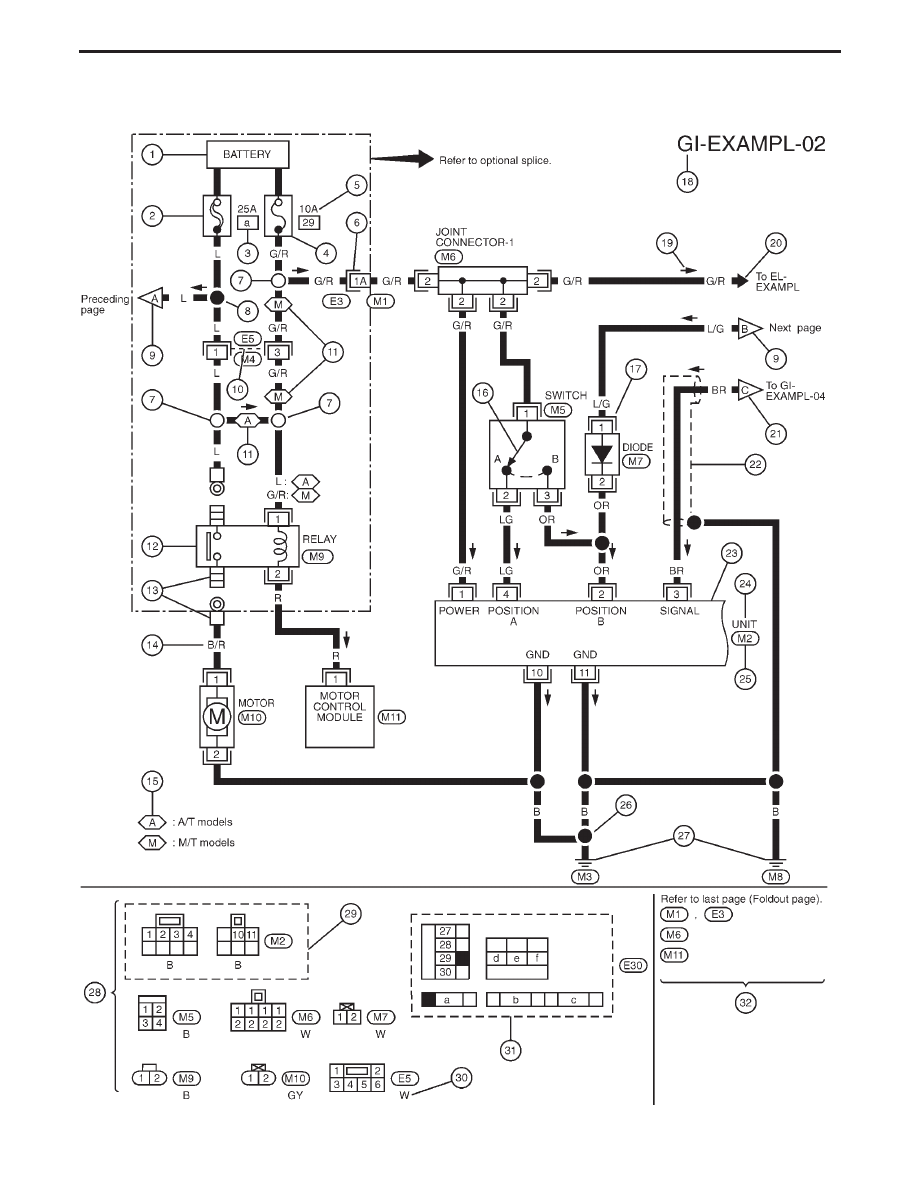
Sample/Wiring Diagram — EXAMPL —
I
For Description, refer to GI-10.
YGI001
HOW TO READ WIRING DIAGRAMS
GI-10
|
|
|
Sample/Wiring Diagram — EXAMPL — I For Description, refer to GI-10. YGI001 HOW TO READ WIRING DIAGRAMS GI-10 |