Nissan Terrano r20e. Manual - part 246
DIAGNOSTIC PROCEDURE 7
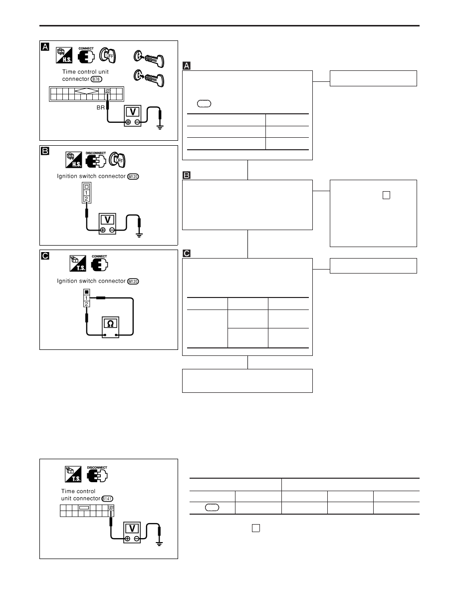
(Ignition switch check)
CHECK IGNITION SWITCH INPUT SIG-
NAL.
Check voltage between control unit termi-
nal
U22
and ground.
NG
E
OK
Ignition switch is OK.
CHECK IGNITION SWITCH POWER
SUPPLY.
Check voltage between ignition switch
harness terminal
q
2
and ground.
Battery voltage should exist.
OK
E
NG
Check the following.
I
10A fuse [No. 16 ,
located in fuse block
(J/B)]
I
Harness for open or
short between ignition
switch and fuse
CHECK IGNITION SWITCH.
1) Disconnect ignition switch connector.
2) Check continuity between ignition
switch terminals.
OK
E
NG
Replace ignition switch.
Check harness for open or short between
control unit and ignition switch.
Condition of key switch
Voltage [V]
Key is inserted
Approx. 12
Key withdrawn
0
Terminals
Condition
Continuity
q
1
-
q
2
Key is
inserted.
Yes
Key is with-
drawn.
No
DIAGNOSTIC PROCEDURE 8
(Ignition switch “ON” circuit check)
Terminals
Ignition switch position
!
@
OFF
ACC
ON
U01
Ground
0V
0V
Battery voltage
If NG, check the following.
I
10A fuse [No.
26
, located in the fuse block (J/B)]
I
Harness for open or short
YEL316D
YEL317D
YEL318D
YEL319D
H
H
H
POWER DOOR LOCK — SUPER LOCK —
Trouble Diagnoses (Cont’d)
EL-167