Nissan Terrano r20e. Manual - part 167
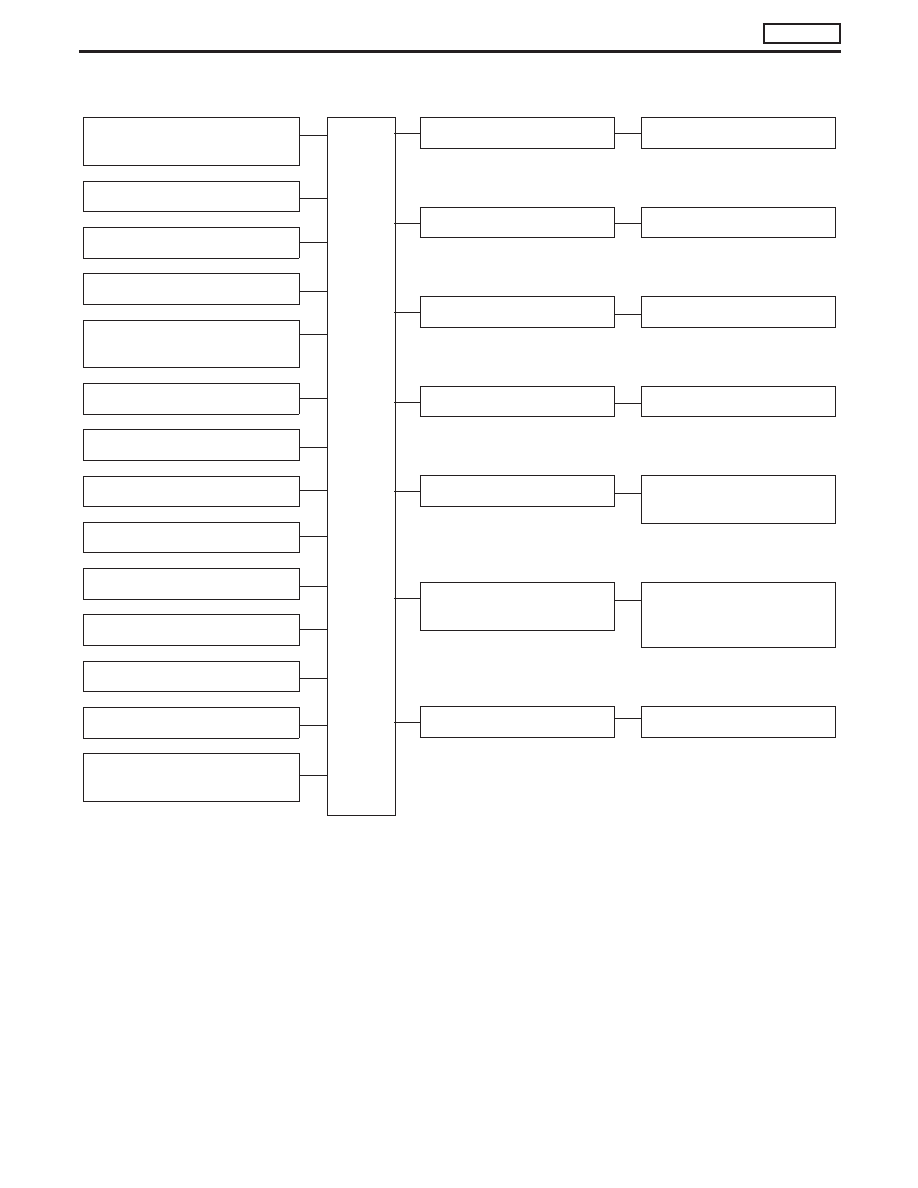
System Chart
Crankshaft position sensor
(TDC)
E
ECM
Control sleeve position sensor
E
Fuel temperature sensor
E
Mass air flow sensor
E
Engine coolant temperature sen-
sor
E
Needle lift sensor
E
Accelerator position sensor
E
Accelerator position switch
E
Air conditioner switch
E
Ignition switch
E
Battery voltage
E
Vehicle speed sensor
E
Brake switch
E
Atmospheric pressure sensor
(inside ECM)
E
E
Fuel injection control
E
Electric governor
E
Fuel injection timing control
E
Injection timing control valve
E
Fuel cut control
E
Fuel cut solenoid valve
E
Glow control system
E
Glow relay & glow lamp
E
On board diagnostic system
E
Malfunction indicator lamp
(On the instrument panel)
E
EGR valve & Throttle control
valve control
E
EGRC-solenoid valve A, B and
throttle control solenoid valve
(models for Germany)
E
Air conditioning cut control
E
Air conditioner relay
ENGINE AND EMISSION CONTROL OVERALL SYSTEM
TD27Ti
EC-305