Nissan Terrano r20e. Manual - part 134


  Index      Nissan     Nissan Terrano r20e - Service and Repair Manual


Search            


Content   ..  132  133  134  135   ..


Nissan Terrano r20e. Manual - part 134


Diagnostic Procedure

1

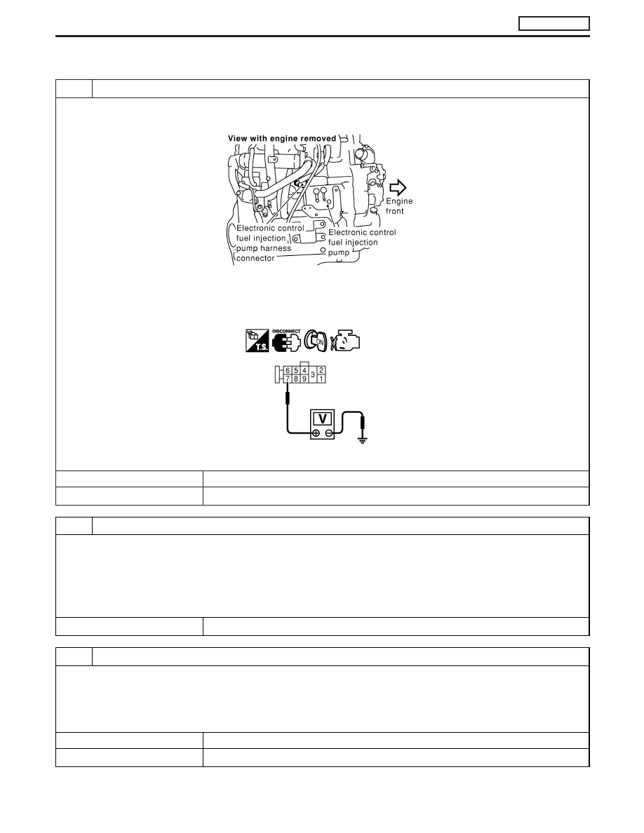
CHECK ELECTRONIC CONTROL FUEL INJECTION PUMP POWER SUPPLY CIRCUIT

1. Turn ignition switch “OFF”.
2. Disconnect electronic control fuel injection pump harness connector.

MEC025E

3. Turn ignition switch “ON”.
4. Check voltage between electronic control fuel injection pump terminal 7 and ground.

MEC977D

Voltage: Battery voltage

OK or NG

OK

E

GO TO 3.

NG

E

GO TO 2.

2

DETECT MALFUNCTIONING PART

Check the following.

I

Harness connectors M787, F66 (LHD models)

I

Harness connectors F108, E225

I

Harness connectors E220, E231

I

Harness connectors M842, F135 (RHD models)

I

Harness for open or short between electronic control fuel injection pump and ECM

I

Harness for open or short between electronic control fuel injection pump and ECM relay

E

Repair open circuit or short to ground or short to power in harness or connectors.

3

CHECK ELECTRONIC CONTROL FUEL INJECTION PUMP GROUND CIRCUIT FOR OPEN AND SHORT

1. Turn ignition switch “OFF”.
2. Check harness continuity between electronic control fuel injection pump terminal 6 and ground. Refer to Wiring Diagram.

Continuity should exist.

3. Also check harness for short to ground and short to power.

OK or NG

OK

E

GO TO 5.

NG

E

GO TO 4.

DTC 0702 P2

TDC PULSE SIG

ZD30DDTi

EC-173

4

DETECT MALFUNCTIONING PART

Check the following.

I

Harness connectors E231, E220

I

Harness for open or short between electronic control fuel injection pump and engine ground

E

Repair open circuit or short to ground or short to power in harness or connectors.

5

CHECK COMMUNICATION LINE FOR OPEN AND SHORT

1. Check continuity between the following terminals. Refer to Wiring Diagram.

MTBL0444

Continuity should exist.

2. Also check harness for short to ground and short to power.

OK or NG

OK

E

GO TO 7.

NG

E

GO TO 6.

6

DETECT MALFUNCTIONING PART

Check the following.

I

Harness connectors E231, E220

I

Harness connectors E227, F106

I

Harness connectors F135, M842 (RHD models)

I

Harness for open or short between electronic control fuel injection pump and ECM

E

Repair open circuit or short to ground or short to power in harness or connectors.

7

CHECK INTERMITTENT INCIDENT

Refer to “TROUBLE DIAGNOSIS FOR INTERMITTENT INCIDENT”, EC-78.

OK or NG

OK

E

Replace electronic control fuel injection pump.

NG

E

Repair open circuit or short to ground or short to power in harness or connectors.

DTC 0702 P2

TDC PULSE SIG

ZD30DDTi

Diagnostic Procedure (Cont’d)

EC-174

Description

SYSTEM DESCRIPTION

The ECM and the electronic control fuel injection pump control unit
(abbreviated as the injection pump control unit) perform the real
time communication (signal exchange).
The ECM transmits the signals of the target fuel injection amount,
target fuel injection timing, and engine speed, etc., and receives the
signals of the pump speed and fuel temperature, etc. from the
injection pump control unit.
By those signals, the injection pump controls the optimum fuel
injection amount and injection timing of the spill valve and timing
control valve.
Injection pump control unit has an on board diagnostic system,
which detects malfunctions related to sensors or actuators built-into
electronic control fuel injection pump. These malfunction informa-
tion are transferred through the line (circuit) from injection pump
control unit to ECM.

FUEL INJECTION AMOUNT CONTROL

In accordance with the target fuel injection amount signal from the
ECM, the injection amount is controlled by controlling the spill valve
in the injection pump and by changing the needle opening time.

FUEL INJECTION TIMING CONTROL

Based on the target fuel injection timing signal from the ECM, the
injection timing is controlled in accordance with the timer spring by
performing the duty control of the timing control valve in the injec-
tion pump and by adjusting the pressure of the timer piston high
pressure chamber.

FUEL TEMPERATURE SENSOR

The sensor detects the fuel temperature in the injection pump and
calibrates the injection amount change by the fuel temperature.

CAM RING POSITION SENSOR

The sensor detects the passing of the protrusion on the sensor
wheel in the injection pump by the semiconductor magnetic resis-
tance element sensor. The cam ring position sensor synchronizes
with the cam ring, and detects the actual advance amount. The
injection pump control unit measures the injection pump revolution
by the signal of the cam ring position sensor.

SEF437Y

DTC 0703 P3

PUMP COMM LINE

ZD30DDTi

EC-175

CONSULT-II Reference Value in Data Monitor
Mode

Remarks: Specification data are reference values.

MONITOR ITEM

CONDITION

SPECIFICATION

FUEL TEMP SEN

I

Engine: After warming up

More than 40°C (104°F)

SPILL/V

I

Engine: After warming up

Approx. 13°CA

INJ TIMG C/V

I

Engine: After warming up,
idle the engine.

Approx. 50 - 70%

DECELER F/CUT

I

Engine: After warm-
ing up

Idle

OFF

BARO SEN

I

Ignition switch: ON

Altitude
Approx. 0 m (0 ft): Approx. 100.62 kPa (1.0062 bar, 1.026 kg/cm

2

, 14.59

psi)
Approx. 1,000 m (3,281 ft): Approx. 88.95 kPa (0.8895 bar, 0.907 kg/cm

2

,

12.90 psi)
Approx. 1,500 m (4,992 ft): Approx. 83.16 kPa (0.8316 bar, 0.848 kg/cm

2

,

12.06 psi)
Approx. 2,000 m (6,562 ft): Approx. 78.36 kPa (0.7836 bar, 0.799 kg/cm

2

,

11.36 psi)

ECM Terminals and Reference Value

Specification data are reference values and are measured between each terminal and ground.

CAUTION:

Do not use ECM ground terminals when measuring input/output voltage. Doing so may damage the
ECM’s transistor. Use a ground other than ECM terminals, such as the ground.

TER-

MINAL

NO.

WIRE

COLOR

ITEM

CONDITION

DATA (DC Voltage)

33

G

Electronic control fuel
injection pump

Engine is running.

Warm-up condition
Idle speed

Approximately 2.5V

40

R

Electronic control fuel
injection pump

Engine is running.

Warm-up condition
Idle speed

Approximately 2.5V

52

Y

Electronic control fuel
injection pump

Engine is running.

Idle speed

Approximately 0.1V

53

OR

Electronic control fuel
injection pump

Engine is running.

Idle speed

Approximately 0.35V

On Board Diagnosis Logic

Malfunction is detected when ....

Check Items (Possible cause)

I

Injection pump control unit receives incorrect voltage signal
from ECM continuously.

I

Harness or connectors
(Electronic control fuel injection pump circuit is open or
shorted.)

I

Electronic control fuel injection pump

DTC 0703 P3

PUMP COMM LINE

ZD30DDTi

EC-176


Content   ..  132  133  134  135   ..