Nissan Terrano r20e. Manual - part 127


  Index      Nissan     Nissan Terrano r20e - Service and Repair Manual


Search            


Content   ..  125  126  127  128   ..


Nissan Terrano r20e. Manual - part 127


Description

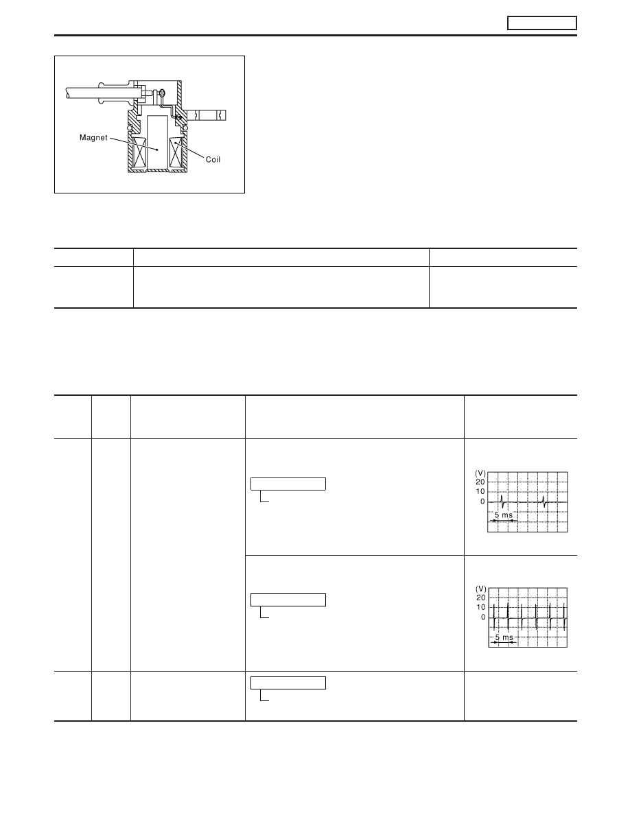
The crankshaft position sensor (TDC) monitors engine speed by
means of signals from the sensing plate (with three protrusions)
installed to the crankshaft pulley. The data signal output is detected
at ATDC 70° and sent to the ECM. The sensor signal is used for
fuel injection control and fuel injection timing control.

CONSULT-II Reference Value in Data Monitor
Mode

Specification data are reference values.

MONITOR ITEM

CONDITION

SPECIFICATION

CKPS

RPM (TDC)

I

Tachometer: Connect

I

Run engine and compare tachometer indication with the CONSULT-II
value.

Almost the same speed as the
CONSULT-II value.

ECM Terminals and Reference Value

Specification data are reference values and are measured between each terminal and ground.

CAUTION:

Do not use ECM ground terminals when measuring input/output voltage. Doing so may damage the
ECM’s transistor. Use a ground other than ECM terminals, such as the ground.

TER-

MINAL

NO.

WIRE

COLOR

ITEM

CONDITION

DATA (DC Voltage and

Pulse Signal)

44

L/G

Crankshaft position sensor
(TDC)

Engine is running.

Warm-up condition
Idle speed

Approximately 0V

SEF333Y

Engine is running.

Warm-up condition
Engine speed is 2,000 rpm

Approximately 0V

SEF334Y

47

L/R

Crankshaft position sensor
(TDC) ground

Engine is running.

Warm-up condition
Idle speed

Approximately 0V

SEF231Z

DTC 0407 CRANK POS SEN (TDC)

ZD30DDTi

EC-145

On Board Diagnosis Logic

Malfunction is detected when ...

Check Items (Possible Cause)

I

An improper signal from the sensor is sent to ECM during
engine running and cranking.

I

Harness or connectors
(The sensor circuit is open.)

I

Crankshaft position sensor (TDC)

DTC Confirmation Procedure

Before performing the following procedure, confirm that bat-
tery voltage is more than 10V.

WITH CONSULT-II

1) Turn ignition switch “ON” and select “DATA MONITOR” mode

with CONSULT-II.

2) Crank engine for at least 1 second.
3) Start engine and run it for at least 2 seconds at idle speed.
4) If DTC is detected, go to “Diagnostic Procedure”, EC-149.

WITHOUT CONSULT-II

1) Crank engine for at least 1 second.
2) Start engine and run it for at least 2 seconds at idle speed.
3) Turn ignition switch “OFF”, wait at least 5 seconds and then turn

“ON”.

4) Perform “Diagnostic Test Mode II (Self-diagnostic results)” with

ECM.

5) If DTC is detected, go to “Diagnostic Procedure”, EC-149.

SEF817Y

DTC 0407 CRANK POS SEN (TDC)

ZD30DDTi

EC-146

Wiring Diagram

LHD MODELS

YEC185A

DTC 0407 CRANK POS SEN (TDC)

ZD30DDTi

EC-147

RHD MODELS

YEC186A

DTC 0407 CRANK POS SEN (TDC)

ZD30DDTi

Wiring Diagram (Cont’d)

EC-148


Content   ..  125  126  127  128   ..