Nissan Terrano r20e. Manual - part 59
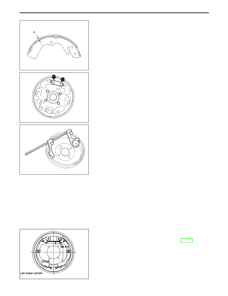
Shoe Replacement
When installing new shoes, springs should be changed as well.
Check lining thickness.
Standard lining thickness:
Trailing: 3.95 mm (0.156 in)
Leading: 8.95 mm (0.352 in)
Lining wear limit (A):
1.52 mm (0.0598 in)
Inspection
WHEEL CYLINDER
I
Check wheel cylinder for leakage.
I
Check for wear, damage and loose conditions.
Replace if any such condition exists.
DRUM
Maximum inner diameter:
282 mm (11.10 in)
Out of roundness:
0.05 mm (0.019 in) or less
I
Contact surface should be fine finished with No. 120 to 150
emery paper.
I
If any scratches or wear are detected, adjust the alignment of
the drum.
I
After brake drum has been completely reconditioned or
replaced, check drum and shoes for proper contact pattern.
Installation
Always
perform
shoe
clearance
adjustment.
Refer
to
“Adjustment”, “PARKING BRAKE CONTROL”, BR-35.
1. Fit adjuster assembly.
SBR021A
SBR018C
SBR019C
EBR089
REAR DRUM BRAKE
BR-33