Nissan Terrano r20e. Manual - part 23


  Index      Nissan     Nissan Terrano r20e - Service and Repair Manual


Search            


Content   ..  21  22  23  24   ..


Nissan Terrano r20e. Manual - part 23


DIAGNOSTIC PROCEDURE

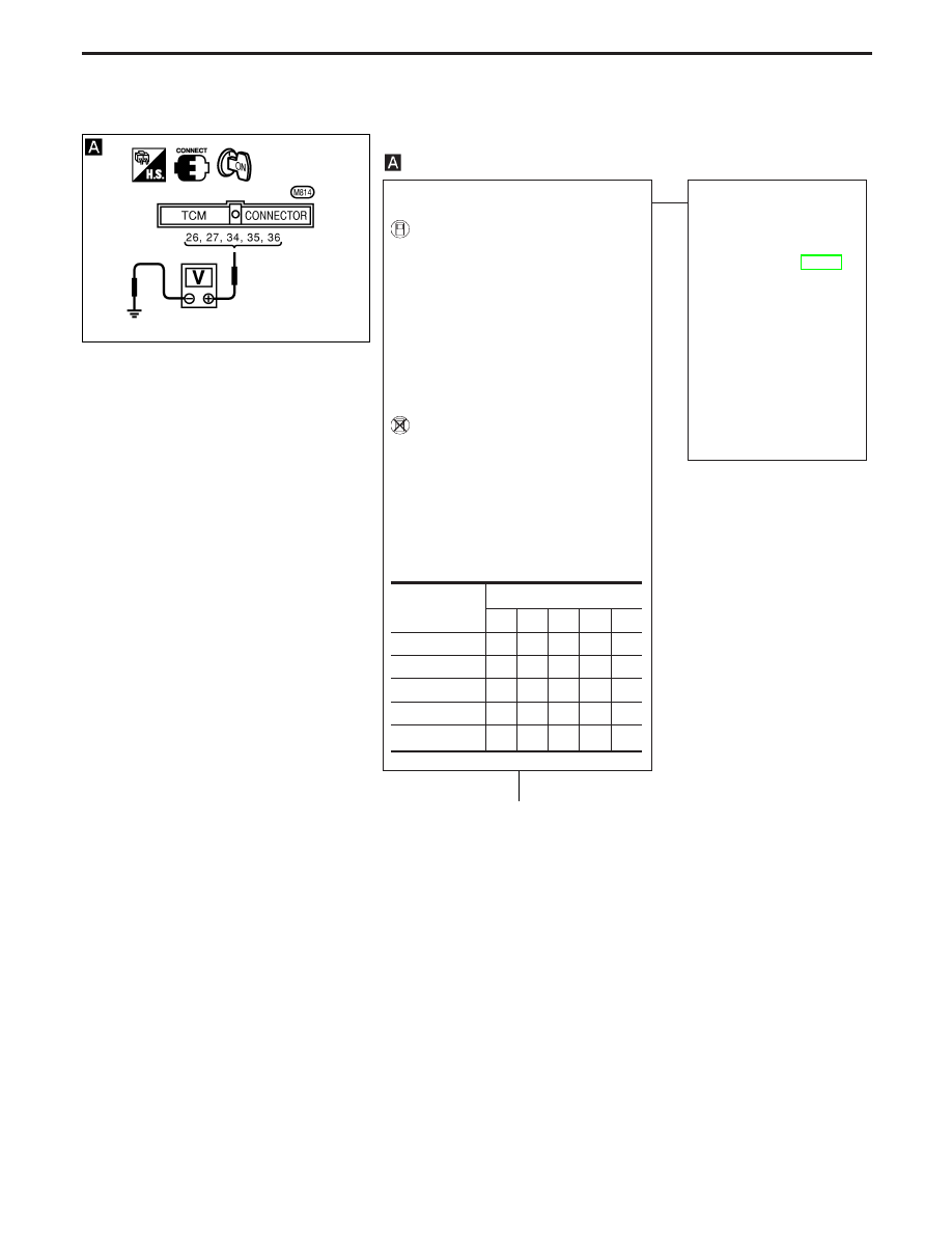
CHECK PARK/NEUTRAL POSITION
SWITCH CIRCUIT.

1. Turn ignition switch to “ON” posi-

tion.
(Do not start engine.)

2. Select “ECU INPUT SIGNALS” in

Data Monitor.

3. Read out “R, N, D, 2 and 1 posi-

tion switches” moving selector
lever to each position.
Check the signal of the selector
lever position is indicated properly.

----------------------------------------------------------------------------------------------------------------------- OR -----------------------------------------------------------------------------------------------------------------------

1. Turn ignition switch to “ON” posi-

tion. (Do not start engine.)

2. Check voltage between TCM ter-

minals

q

26

,

q

27

,

q

34

,

q

35

,

q

36

and

ground while moving selector
lever through each position.
Voltage:

B: Battery voltage
0: 0V

OK

E

NG

Check the following items:

I

Park/neutral position
switch
Refer to “COMPONENT
INSPECTION”, AT-114.

I

Harness for short or
open between ignition
switch and park/neutral
position switch (Main
harness)

I

Harness for short or
open between park/
neutral position switch
and TCM (Main harness)

I

Diode

q

A

(Go to next page.)

Lever position

Terminal No.

q

36

q

35

q

34

q

27

q

26

P, N

B

0

0

0

0

R

0

B

0

0

0

D

0

0

B

0

0

2

0

0

0

B

0

1

0

0

0

0

B

YAT326

H

TROUBLE DIAGNOSIS FOR NON-DETECTABLE ITEMS

Park/neutral Position, Overdrive Control or
Throttle (Accelerator) Position Switches
(Cont’d)

AT-89

q

A

CHECK OVERDRIVE CONTROL
SWITCH CIRCUIT.

1. Turn ignition switch to “ON” posi-

tion.
(Do not start engine.)

2. Select “ECU INPUT SIGNALS” in

Data Monitor.

3. Read out “OVERDRIVE SWITCH”.

Check the signal of the overdrive
control switch is indicated prop-
erly.
(Overdrive control switch “ON”
displayed on CONSULT-II means
overdrive “OFF”.)

----------------------------------------------------------------------------------------------------------------------- OR -----------------------------------------------------------------------------------------------------------------------

1. Turn ignition switch to “ON” posi-

tion.
(Do not start engine.)

2. Check voltage between TCM ter-

minal

q

22

and ground when over-

drive control switch is “ON” and
“OFF”.

OK

E

NG

Check the following items.

I

Overdrive control switch
Refer to “COMPONENT
INSPECTION”, AT-114.

I

Harness for short or
open between TCM and
overdrive control switch
(Main harness)

I

Harness for short or
open of ground circuit for
overdrive control switch
(Main harness)

q

B

(Go to next page.)

Switch position

Voltage

ON

Battery voltage

OFF

1V or less

YAT327

H

H

TROUBLE DIAGNOSIS FOR NON-DETECTABLE ITEMS

Park/neutral Position, Overdrive Control or
Throttle (Accelerator) Position Switches
(Cont’d)

AT-90

q

B

CHECK THROTTLE (ACCELERATOR)
POSITION SWITCH CIRCUIT.

1. Turn ignition switch to “ON” posi-

tion.
(Do not start engine.)

2. Select “ECU INPUT SIGNALS” in

Data Monitor.

3. Read out “CLOSED THL/SW” and

“W/O THRL/P-SW” depressing
and releasing accelerator pedal.
Check the signal of throttle (accel-
erator) position switch is indicated
properly.

----------------------------------------------------------------------------------------------------------------------- OR -----------------------------------------------------------------------------------------------------------------------

1. Turn ignition switch to “ON” posi-

tion.
(Do not start engine.)

2. Check voltage between TCM ter-

minals

q

16

,

q

17

and ground while

depressing, and releasing accel-
erator pedal slowly. (after warming
up engine)

OK

E

NG

Check the following items:

I

Throttle (accelerator)
position switch
Refer to “COMPONENT
INSPECTION”, AT-114.

I

Harness for short or
open between ignition
switch and throttle
(accelerator) position
switch (Main harness)

I

Harness for short or
open between throttle
(accelerator) position
switch and TCM (Main
harness)

Perform “DIAGNOSTIC PROCEDURE”,
AT-89.

OK

E

NG

1. Perform TCM input/

output signal inspection.

2. If NG, recheck TCM pin

terminals for damage or
loose connection with
harness connector.

INSPECTION END

Accelerator

pedal condi-

tion

Data monitor

CLOSED

THL/SW

W/O THRL/

P-SW

Released

ON

OFF

Fully

depressed

OFF

ON

Accelerator

pedal

condition

Voltage

Terminal

No.

q

16

Terminal No.

q

17

Released

Battery
voltage

1V or less

Fully

depressed

1V or less

Battery
voltage

YAT328

YAT329

H

H

H

TROUBLE DIAGNOSIS FOR NON-DETECTABLE ITEMS

Park/neutral Position, Overdrive Control or
Throttle (Accelerator) Position Switches
(Cont’d)

AT-91

COMPONENT INSPECTION

Overdrive control switch

I

Check continuity between terminals

q

1

and

q

2

.

Switch position

Continuity

ON

No

OFF

Yes

A/T mode switch

I

Check continuity between terminals

q

1

, (

q

3

) and

q

2

.

Switch position

Terminal No.

Continuity

S

ON

q

1

q

2

Yes

OFF

No

*

ON

q

2

q

3

Yes

OFF

No

Park/neutral position switch

1. Check continuity between terminals

q

1

and

q

2

and between

terminals

q

3

and

q

4

,

q

5

,

q

6

,

q

7

,

q

8

,

q

9

while moving man-

ual shaft through each position.

Lever position

Terminal No.

P

q

1

q

2

q

3

q

7

R

q

3

q

8

N

q

1

q

2

q

3

q

9

D

q

3

q

6

2

q

3

q

5

1

q

3

q

4

2. If NG, check again with manual control linkage disconnected

from manual shaft of A/T assembly. Refer to step 1.

3. If OK on step 2, adjust manual control linkage. Refer to AT-112.

4. If NG on step 2, remove park/neutral position switch from A/T

and check continuity of park/neutral position switch terminals.
Refer to step 1.

5. If OK on step 4, adjust park/neutral position switch. Refer to

AT-114.

6. If NG on step 4, replace park/neutral position switch.

NAT265

NAT266

SAT517GB

NAT267

NAT268

TROUBLE DIAGNOSIS FOR NON-DETECTABLE ITEMS

Park/neutral Position, Overdrive Control or
Throttle (Accelerator) Position Switches
(Cont’d)

AT-92


Content   ..  21  22  23  24   ..