Nissan Terrano r20e. Manual - part 20


  Index      Nissan     Nissan Terrano r20e - Service and Repair Manual


Search            


Content   ..  18  19  20  21   ..


Nissan Terrano r20e. Manual - part 20


DIAGNOSTIC PROCEDURE

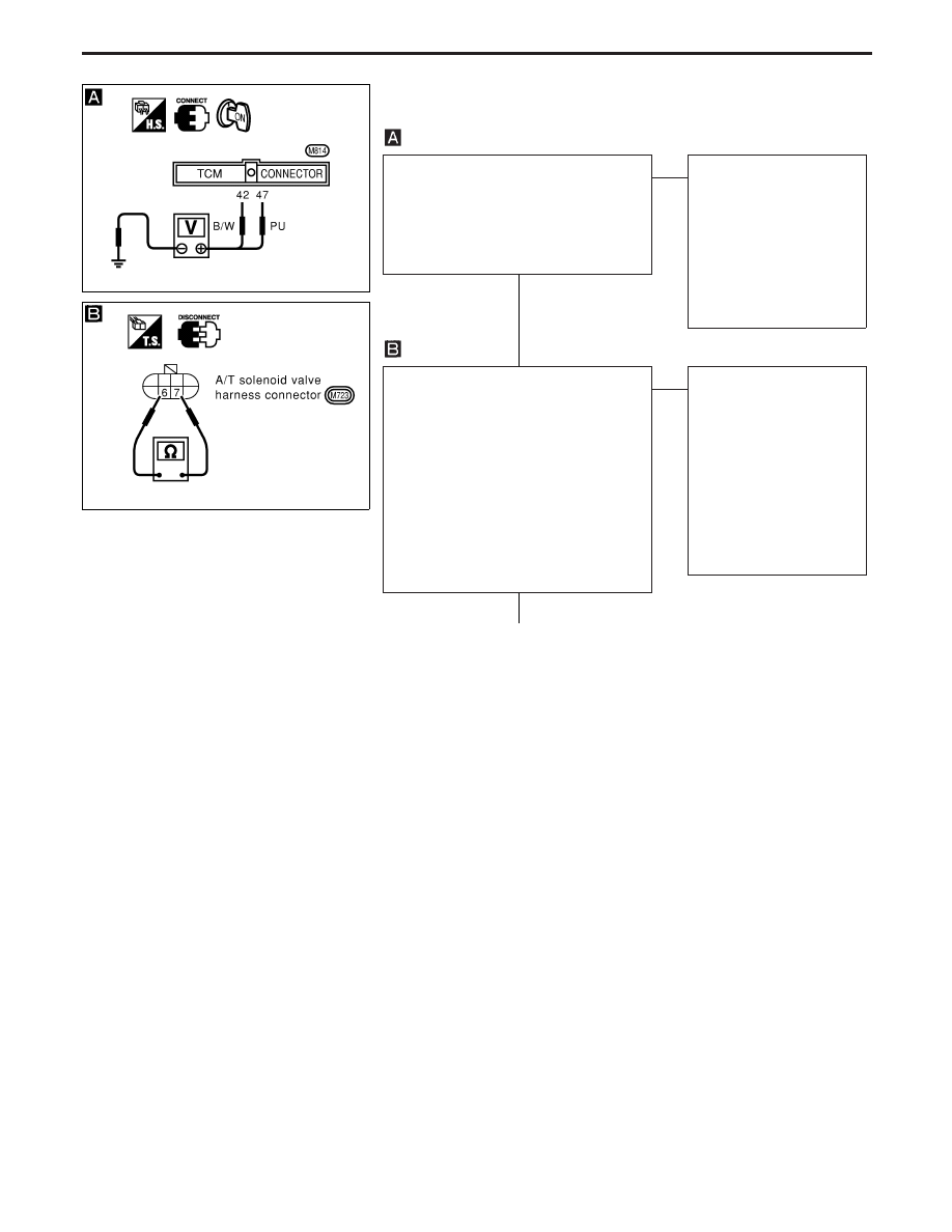
CHECK TCM POWER SOURCE.
1. Turn ignition switch to “ON” position.

(Do not start engine.)

2. Check voltage between TCM terminals

q

42

,

q

47

and ground.

Battery voltage should exist.

OK

E

NG

Check the following items:

I

Harness for short or
open between ignition
switch and TCM (Main
harness)

I

Ignition switch and fuse
Refer to EL section
(“POWER SUPPLY
ROUTING”).

CHECK A/T FLUID TEMPERATURE
SENSOR WITH TERMINAL CORD
ASSEMBLY.
1. Turn ignition switch to “OFF” position.
2. Disconnect terminal cord assembly

connector in engine compartment.

3. Check resistance between terminals

q

6

and

q

7

when A/T is cold.

Resistance:

Cold [20°C (68°F)]

Approximately 2.5 k

4. Reinstall any part removed.

OK

E

NG

1. Remove oil pan.
2. Check the following

items:

I

A/T fluid temperature
sensor
Refer to “COMPONENT
INSPECTION” on next
page.

I

Harness of terminal cord
assembly for short or
open

q

A

(Go to next page.)

YAT316

YAT317

H

H

TROUBLE DIAGNOSIS FOR BATT/FLUID TEMP SEN

A/T Fluid Temperature Sensor and TCM Power
Source (Cont’d)

AT-77

q

A

CHECK INPUT SIGNAL OF A/T FLUID
TEMPERATURE SENSOR.

1. Start engine.

2. Select “ECU INPUT SIGNALS” in

Data Monitor.

3. Read out the value of “FLUID

TEMP SE”.
Voltage:
Cold [20°C (68°F)]

Hot [80°C (176°F)]:

Approximately
1.5V

0.5V

----------------------------------------------------------------------------------------------------------------------- OR -----------------------------------------------------------------------------------------------------------------------

1. Start engine.

2. Check voltage between TCM ter-

minal

q

47

and ground while warm-

ing up A/T.
Voltage:
Cold [20°C (68°F)]

Hot [80°C (176°F)]:

Approximately
1.5V

0.5V

OK

E

NG

Check the following item:

I

Harness for short or
open between TCM and
terminal cord assembly
(Main harness)

Perform “SELF-DIAGNOSIS CODE CON-
FIRMATION PROCEDURE”, AT-76.

OK

E

NG

1. Perform TCM input/

output signal inspection.

2. If NG, recheck TCM pin

terminals for damage or
loose connection with
harness connector.

INSPECTION END

COMPONENT INSPECTION

A/T fluid temperature sensor

I

For removal, refer to AT-113.

I

Check resistance between terminals

q

6

and

q

7

while changing

temperature as shown at left.

Temperature °C (°F)

Resistance

20 (68)

Approximately 2.5 k

80 (176)

Approximately 0.3 k

YAT318

YAT319

H

H

H

TROUBLE DIAGNOSIS FOR BATT/FLUID TEMP SEN

A/T Fluid Temperature Sensor and TCM Power
Source (Cont’d)

AT-78

Wiring Diagram — AT — ENGSS

YAT271

TROUBLE DIAGNOSIS FOR ENGINE SPEED SIG

AT-79

Engine Speed Signal

DESCRIPTION

The engine speed signal is sent from the ECM to the TCM.

ON BOARD DIAGNOSIS LOGIC

Diagnostic trouble code

Malfunction is detected when ...

Check items

(Possible cause)

:

ENGINE SPEED SIG

TCM does not receive the proper volt-
age signal from ECM.

I

Harness or connectors
(The sensor circuit is open or
shorted.)

:

9th judgement flicker

SELF-DIAGNOSIS CODE CONFIRMATION PROCEDURE

After the repair, perform the following procedure to confirm the
malfunction is eliminated.

1)

Start engine.

2)

Select “SELF-DIAG RESULTS” mode with CONSULT-II.

3)

Drive vehicle under the following conditions:
Selector lever in “D” position, vehicle speed higher than
10 km/h (6 MPH), throttle opening greater than 1/8 of the
full throttle position and driving for more than 10 sec-
onds.

------------------------------------------------------------------------------------------------------------------------------------------------------------------------------------------------------------------------------------------------------------ OR ------------------------------------------------------------------------------------------------------------------------------------------------------------------------------------------------------------------------------------------------------------

1)

Start engine.

2)

Drive vehicle under the following conditions:
Selector lever in “D” position, vehicle speed higher than
10 km/h (6 MPH), throttle opening greater than 1/8 of the
full throttle position and driving for more than 10 sec-
onds.

3)

Perform self-diagnosis.
Refer to SELF-DIAGNOSTIC PROCEDURE (Without
CONSULT-II), AT-15.

SAT823H

TROUBLE DIAGNOSIS FOR ENGINE SPEED SIG

AT-80


Content   ..  18  19  20  21   ..