Nissan Titan. Manual - part 619
 

  Index      Nissan     Nissan Titan (2014 year) - Service and Repair Manual


Search            


Content   ..  617  618  619  620   ..


Nissan Titan. Manual - part 619


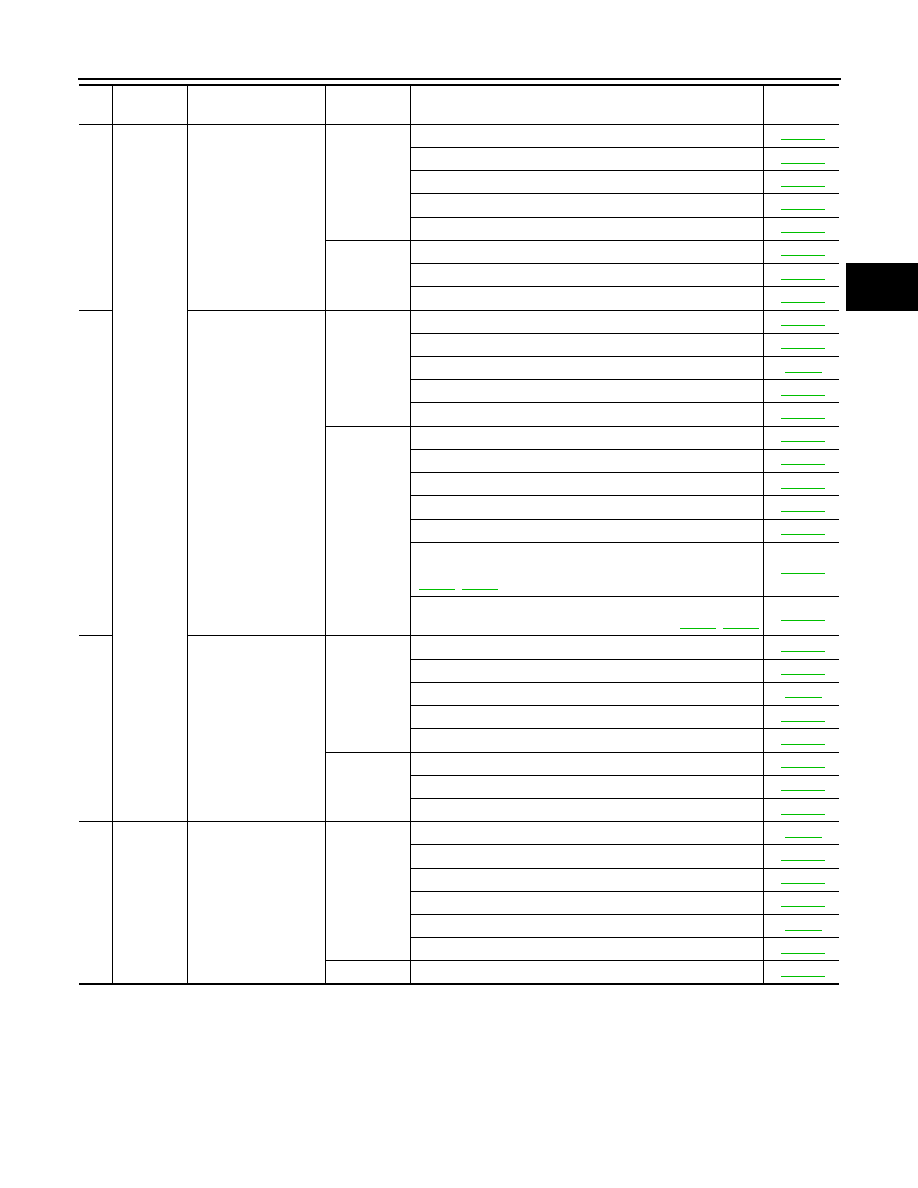
SYSTEM SYMPTOM

TM-159

< SYMPTOM DIAGNOSIS >

C

E

F

G

H

I

J

K

L

M

A

B

TM

N

O

P

44

Slips/Will 
Not En-
gage

Vehicle cannot run in 
all positions.

ON vehicle

1. Fluid level and state

TM-172

2. Line pressure test

TM-181

3. Transmission range switch

TM-201

4. Control cable adjustment

TM-190

5. Control valve with TCM

TM-201

OFF vehicle

6. Oil pump assembly

TM-247

7. Gear system

TM-217

8. Output shaft

TM-229

45

With selector lever in 
“D” position, driving is 
not possible.

ON vehicle

1. Fluid level and state

TM-172

2. Line pressure test

TM-181

3. Transmission range switch

TM-53

4. Control cable adjustment

TM-190

5. Control valve with TCM

TM-201

OFF vehicle

6. Torque converter

TM-229

7. Oil pump assembly 

TM-247

8. 1st one-way clutch

TM-256

9. Gear system

TM-217

10. Reverse brake

TM-229

11. Forward one- way clutch (Parts behind drum support is 
impossible to perform inspection by disassembly. Refer to 

TM-10

TM-11

TM-229

12. Forward brake (Parts behind drum support is impossible 
to perform inspection by disassembly. Refer to 

TM-10

TM-11

TM-229

46

With selector lever in 
“R” position, driving is 
not possible.

ON vehicle

1. Fluid level and state

TM-172

2. Line pressure test

TM-181

3. Transmission range switch

TM-53

4. Control cable adjustment

TM-190

5. Control valve with TCM

TM-201

OFF vehicle

6. Gear system

TM-217

7. Output shaft

TM-229

8. Reverse brake

TM-229

47

Does not 
change

Does not change M

→ M

4

.

ON vehicle

1. Transmission range switch

TM-53

2. Fluid level and state

TM-172

3. Control cable adjustment

TM-190

4. Manual mode switch

TM-102

5. CAN communication line

TM-48

6. Control valve with TCM

TM-201

OFF vehicle

7. Front brake (brake band)

TM-217

No.

Items

Symptom

Condition

Diagnostic Item

Reference 

page

TM-160

< SYMPTOM DIAGNOSIS >

SYSTEM SYMPTOM

48

Does not 
change

Does not change M

4

→ M

3

.

ON vehicle

1. Transmission range switch

TM-53

2. Fluid level and state

TM-172

3. Control cable adjustment

TM-190

4. Manual mode switch

TM-102

5. CAN communication line

TM-48

6. Control valve with TCM

TM-201

OFF vehicle

7. Front brake (brake band)

TM-217

8. Input clutch

TM-251

49

Does not change M

3

→ M

2

.

ON vehicle

1. Transmission range switch

TM-53

2. Fluid level and state

TM-172

3. Control cable adjustment

TM-190

4. Manual mode switch

TM-102

5. CAN communication line

TM-48

6. Control valve with TCM

TM-201

OFF vehicle

7. Front brake (brake band)

TM-217

8. Input clutch

TM-251

9. High and low reverse clutch

TM-261

50

Does not change M

2

→ M

1

.

ON vehicle

1. Transmission range switch

TM-53

2. Fluid level and state

TM-172

3. Control cable adjustment

TM-190

4. Manual mode switch

TM-102

5. CAN communication line

TM-48

6. Control valve with TCM

TM-201

OFF vehicle

7. Input clutch

TM-251

8. High and low reverse clutch

TM-261

9. Direct clutch

TM-263

51

Cannot be changed to 
manual mode.

ON vehicle

1. Manual mode switch

TM-102

2. Input speed sensor

TM-56

3. CAN communication line

TM-48

52

Others

Shift point is high in 
“D” position.

ON vehicle

1. Output speed sensor and vehicle speed signal

TM-58

TM-84

2. Accelerator pedal position sensor

TM-79

3. CAN communication line

TM-48

4. ATF temperature sensor

TM-81

5. Control valve with TCM

TM-201

No.

Items

Symptom

Condition

Diagnostic Item

Reference 

page

SYSTEM SYMPTOM

TM-161

< SYMPTOM DIAGNOSIS >

C

E

F

G

H

I

J

K

L

M

A

B

TM

N

O

P

53

Others

Shift point is low in “D” 
position.

ON vehicle

1. Output speed sensor and vehicle speed signal

TM-58

TM-84

2. Accelerator pedal position sensor

TM-79

3. CAN communication line

TM-48

4. Control valve with TCM

TM-201

54

Judder occurs during 
lock-up.

ON vehicle

1. Fluid level and state

TM-172

2. Engine speed signal

TM-61

3. Input speed sensor

TM-56

4. Output speed sensor and vehicle speed signal

TM-58

TM-84

5. Accelerator pedal position sensor

TM-79

6. CAN communication line

TM-48

7. Torque converter clutch solenoid valve

TM-73

8. Control valve with TCM

TM-201

OFF vehicle

9. Torque converter

TM-229

55

Strange noise in “R” 
position.

ON vehicle

1. Fluid level and state

TM-172

2. Engine speed signal

TM-61

3. CAN communication line

TM-48

4. Control valve with TCM

TM-201

OFF vehicle

5. Torque converter

TM-229

6. Oil pump assembly

TM-247

7. Gear system

TM-217

8. High and low reverse clutch

TM-261

9. Reverse brake

TM-229

56

Strange noise in “N” 
position.

ON vehicle

1. Fluid level and state

TM-172

2. Engine speed signal

TM-61

3. CAN communication line

TM-48

4. Control valve with TCM

TM-201

OFF vehicle

5. Torque converter

TM-229

6. Oil pump assembly

TM-247

7. Gear system

TM-217

57

Strange noise in “D” 
position.

ON vehicle

1. Fluid level and state

TM-172

2. Engine speed signal

TM-61

3. CAN communication line

TM-48

4. Control valve with TCM

TM-201

OFF vehicle

5. Torque converter

TM-229

6. Oil pump assembly

TM-247

7. Gear system

TM-217

8. Forward brake (Parts behind drum support is impossible to 
perform inspection by disassembly. Refer to 

TM-10

TM-11

TM-229

No.

Items

Symptom

Condition

Diagnostic Item

Reference 

page

TM-162

< SYMPTOM DIAGNOSIS >

SYSTEM SYMPTOM

58

Others

Vehicle dose not de-
celerate by engine 
brake.

ON vehicle

1. Transmission range switch

TM-53

2. Fluid level and state

TM-172

3. Control cable adjustment

TM-190

4. 1st position switch (floor shift models), manual mode switch 
(column shift models)

TM-116


(floor shift 

models), 

TM-102


(column 

shift mod-

els)

5. CAN communication line

TM-48

6. Control valve with TCM

TM-201

OFF vehicle

7. Input clutch

TM-251

8. High and low reverse clutch

TM-261

9. Direct clutch

TM-263

59

Engine brake does not 
operate in “2” position.

ON vehicle

1. Transmission range switch

TM-53

2. Fluid level and state

TM-172

3. Control cable adjustment

TM-190

5. CAN communication line

TM-48

6. Control valve with TCM

TM-201

OFF vehicle

7. Front brake (brake band)

TM-217

8. Input clutch

TM-251

9. High and low reverse clutch

TM-261

60

Engine brake does not 
operate in “1” position.

ON vehicle

1. Transmission range switch

TM-53

2. Fluid level and state

TM-172

3. Control cable adjustment

TM-190

4. 1st position switch

TM-116

5. CAN communication line

TM-48

6. Control valve with TCM

TM-201

OFF vehicle

7. Input clutch

TM-251

8. High and low reverse clutch

TM-261

9. Direct clutch

TM-263

61

Engine brake does not 
work M

→ M4.

ON vehicle

1. Transmission range switch

TM-53

2. Fluid level and state

TM-172

3. Control cable adjustment

TM-190

4. Manual mode switch

TM-102

5. CAN communication line

TM-48

6. Control valve with TCM

TM-201

OFF vehicle

7. Front brake (brake band)

TM-217

8. Input clutch

TM-251

No.

Items

Symptom

Condition

Diagnostic Item

Reference 

page


Content   ..  617  618  619  620   ..