Nissan Titan. Manual - part 588
A/T SHIFT LOCK SYSTEM
TM-35
< SYSTEM DESCRIPTION >
C
E
F
G
H
I
J
K
L
M
A
B
TM
N
O
P
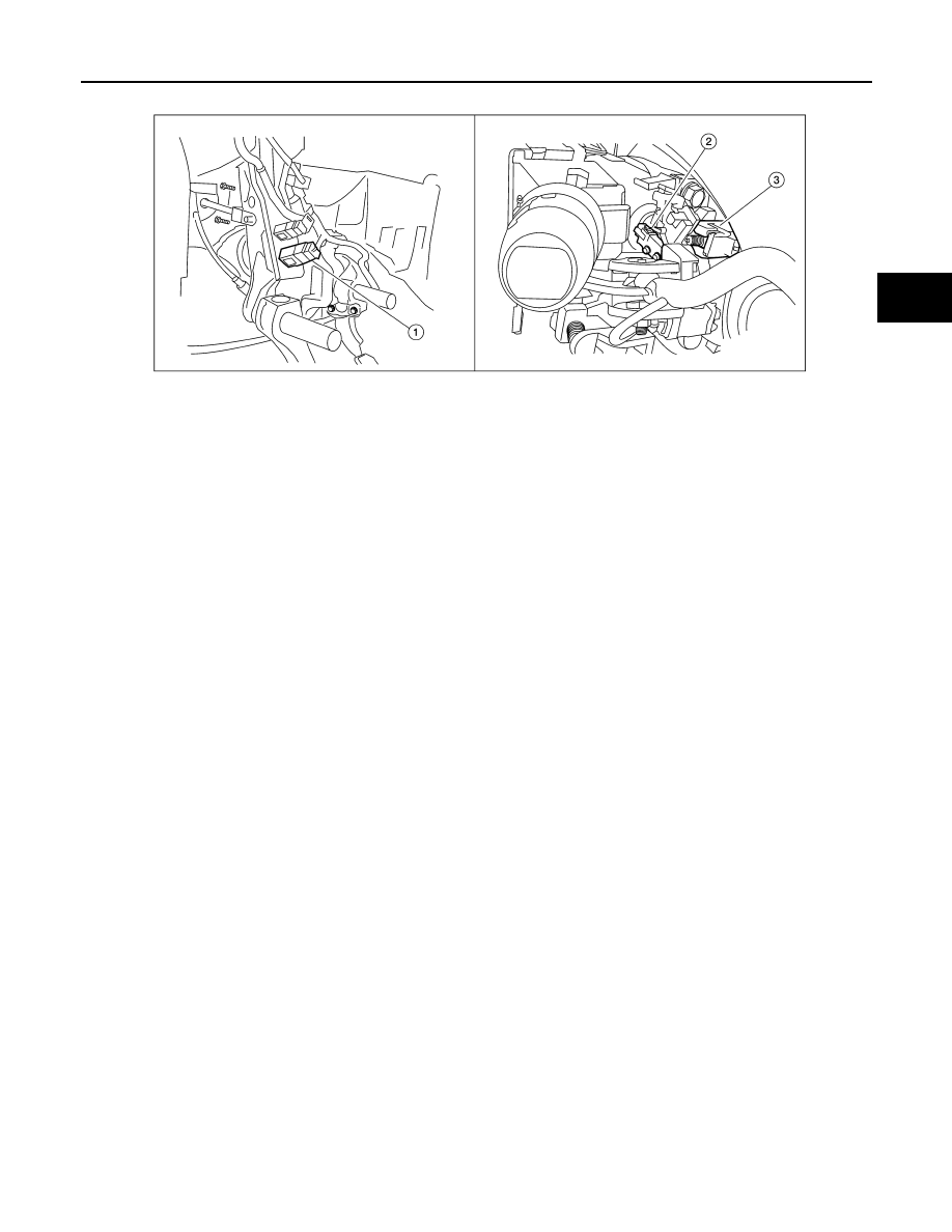
1.
Stop lamp switch
2.
Park position switch
3.
Shift lock solenoid
ALDIA0213ZZ
|
|
|
A/T SHIFT LOCK SYSTEM TM-35 < SYSTEM DESCRIPTION > C E F G H I J K L M A B TM N O P 1. Stop lamp switch 2. Park position switch 3. Shift lock solenoid ALDIA0213ZZ |