Nissan Titan. Manual - part 532
SEC-40
< ECU DIAGNOSIS INFORMATION >
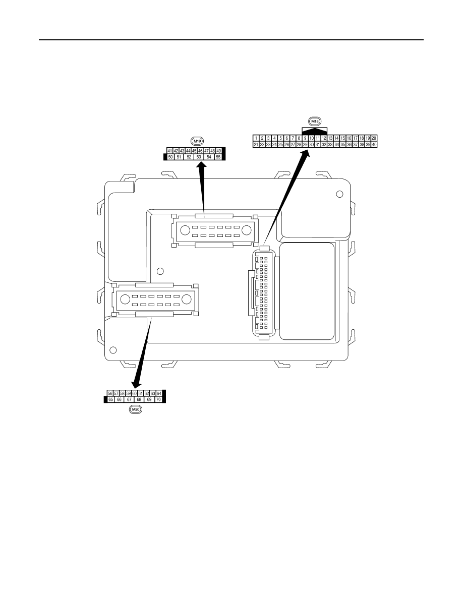
BCM (BODY CONTROL MODULE)
Terminal Layout
INFOID:0000000009878901
Physical Values
INFOID:0000000009878902
LIIA2443E
|
|
|
SEC-40 < ECU DIAGNOSIS INFORMATION > BCM (BODY CONTROL MODULE) Terminal Layout INFOID:0000000009878901 Physical Values INFOID:0000000009878902 LIIA2443E |