Nissan Titan. Manual - part 467


  Index      Nissan     Nissan Titan (2014 year) - Service and Repair Manual


Search            


Content   ..  465  466  467  468   ..


Nissan Titan. Manual - part 467


ENCODER CIRCUIT CHECK FRONT (KING CAB)

PWC-41

< DTC/CIRCUIT DIAGNOSIS >

C

D

E

F

G

H

I

J

L

M

A

B

PWC

N

O

P

1.

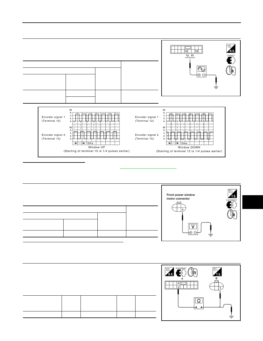
 CHECK ENCODER SIGNAL

1. Turn ignition switch ON.

2. Check signal between power window and door lock/unlock

switch RH connector and ground with oscilloscope.

Is the inspection result normal?

YES

>> Check intermittent incident. Refer to 

GI-42, "Intermittent Incident"

.

NO

>> GO TO 2

2.

 CHECK FRONT POWER WINDOW MOTOR RH POWER SUPPLY

1. Disconnect front power window motor RH.

2. Check voltage between front power window motor RH connector

and ground.

Is the measurement value within the specification?

YES

>> GO TO 4

NO

>> GO TO 3

3.

 CHECK HARNESS CONTINUITY 1

1. Turn ignition switch OFF.

2. Disconnect power window and door lock/unlock switch RH.

3. Check continuity between power window and door lock/unlock

switch RH connector (A) and front power window motor RH con-

nector (B).

4. Check continuity between power window and door lock/unlock

switch RH connector (A) and ground.

Terminals

Signal

(Reference value)

(+)

(–)

 Power window and door 

lock/unlock switch RH 

connector

Terminal

D105

12

Ground

Refer to following 

signal

15

ALKIA0322ZZ

ALKIA0305GB

Terminal

Voltage (V)

(Approx.)

(+)

(–)

 Front power window 

motor RH connector

Terminal

D105

4

Ground

10

WIIA0513E

Power window and 

door lock/unlock 

switch RH connector

Terminal

Front power window 
motor RH connector

Terminal

Continuity

D105 (A)

4

D104 (B)

4

Yes

ALKIA1023ZZ

PWC-42

< DTC/CIRCUIT DIAGNOSIS >

ENCODER CIRCUIT CHECK FRONT (KING CAB)

Is the inspection result normal?

YES

>> Replace power window and door lock/unlock switch RH. Refer to 

PWC-116, "Removal and Instal-

lation"

NO

>> Repair or replace harness.

4.

 CHECK GROUND CIRCUIT

1. Turn ignition switch OFF.

2. Check continuity between front power window motor RH con-

nector and ground.

Is the inspection result normal?

YES

>> GO TO 6

NO

>> GO TO 5

5.

 CHECK HARNESS CONTINUITY 2

1. Disconnect power window and door lock/unlock switch RH.

2. Check continuity between power window and door lock/unlock

switch RH connector and front power window motor RH connec-

tor.

Is the inspection result normal?

YES

>> Replace power window and door lock/unlock switch RH.

Refer to 

PWC-116, "Removal and Installation"

NO

>> Repair or replace harness.

6.

 CHECK HARNESS CONTINUITY 3

1. Disconnect power window and door lock/unlock switch RH.

2. Check continuity between power window and door lock/unlock

switch RH connector (A) and front power window motor RH con-

nector (B).

3. Check continuity between power window and door lock/unlock

switch RH connector (A) and ground.

Power window and door lock/

unlock switch RH connector

Terminal

Ground

Continuity

D105 (A)

4

No

Front power window motor RH 

connector

Terminal

Ground

Continuity 

D104

6

Yes

LIIA0923E

Power window and door 

lock/unlock switch RH 

connector

Terminal

Front power window 
motor RH connector

Terminal

Continuity

D105

3

D104

6

Yes

LIIA1264E

Power window and 

door lock/unlock 

switch RH connector

Terminal

Front power window 
motor RH connector

Terminal

Continuity

D105 (A)

12

D104 (B)

3

Yes

15

5

Power window and door 

lock/unlock switch RH con-

nector

Terminal

Ground

Continuity

D105 (A)

12

No

15

ALKIA1024ZZ

ENCODER CIRCUIT CHECK FRONT (KING CAB)

PWC-43

< DTC/CIRCUIT DIAGNOSIS >

C

D

E

F

G

H

I

J

L

M

A

B

PWC

N

O

P

Is the inspection result normal?

YES

>> Replace front power window motor RH. Refer to 

GW-18, "Removal and Installation"

.

NO

>> Repair or replace harness.

PWC-44

< DTC/CIRCUIT DIAGNOSIS >

DOOR SWITCH

DOOR SWITCH

Description

INFOID:0000000009878985

Detects door open/close condition and transmits the signal to BCM.

Component Function Check

INFOID:0000000009878986

1.

 CHECK FRONT DOOR SWITCH INPUT SIGNAL

Check (“DOOR SW-DR” and “DOOR SW-AS”) in “DATA MONITOR” mode with CONSULT. Refer to 

BCS-24,

"RETAINED PWR : CONSULT Function (BCM - RETAINED PWR)"

.

Is the inspection result normal?

YES

>> Front door switch circuit is OK.

NO

>> Refer to 

PWC-44, "Diagnosis Procedure (Crew Cab)"

.

Diagnosis Procedure (Crew Cab)

INFOID:0000000009878987

Regarding Wiring Diagram information, refer to 

PWC-88, "Wiring Diagram - Crew Cab"

.

1.

 CHECK FRONT DOOR SWITCH

Check voltage between BCM connector and ground.

Is the measurement value within the specification?

YES

>> Replace BCM. Refer to 

BCS-52, "Removal and Installation"

.

NO

>> GO TO 2

2.

 CHECK HARNESS CONTINUITY

Monitor item

Condition

DOOR SW-DR

OPEN

: ON

CLOSE

: OFF

DOOR SW-AS

OPEN

: ON

CLOSE

: OFF

Terminals

Door condition

Voltage (V)

(Approx.)

(+)

(–)

BCM

 connector

Terminal 

M18

12

Ground

Front door 

RH

OPEN

0

CLOSE

Battery voltage

M19

47

Front door 

LH

OPEN

0

CLOSE

Battery voltage

LIIA0946E


Content   ..  465  466  467  468   ..