Nissan Titan. Manual - part 425


  Index      Nissan     Nissan Titan (2014 year) - Service and Repair Manual


Search            


Content   ..  423  424  425  426   ..


Nissan Titan. Manual - part 425


INTAKE DOOR MOTOR

HAC-205

< DTC/CIRCUIT DIAGNOSIS >

[MANUAL A/C (TYPE 2)]

C

D

E

F

G

H

J

K

L

M

A

B

HAC

N

O

P

INTAKE DOOR MOTOR

System Description

INFOID:0000000009882581

SYSTEM DESCRIPTION

SYMPTOM:

• Intake door motor does not operate normally.

• Intake door does not change.

SYSTEM DESCRIPTION

Component Parts

Intake door control system components are:

• Front air control

• Intake door motor (PBR built into the intake door motor)

• Intake sensor

System Operation

The intake door control determines the intake door position based on the position of the recirculation switch.

When the recirculation switch is depressed the intake door motor rotates closing off the fresh air inlet and

recirculating the cabin air. If the recirculation switch is depressed again, the intake door motor rotates in the

opposite direction, again allowing fresh air into the cabin.

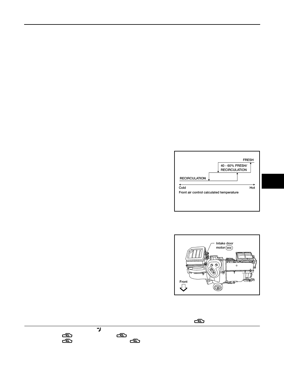
Intake Door Control Specification

COMPONENT DESCRIPTION

Intake door motor

The intake door motor is attached to the intake unit. It rotates so that

air is drawn from inlets set by the front air control. Motor rotation is

conveyed to a lever which activates the intake door.

Intake Door Motor Component Function Check

INFOID:0000000009882582

INSPECTION FLOW

1.

CONFIRM SYMPTOM BY PERFORMING OPERATIONAL CHECK - REC (

)

1. Press the vent mode switch (

).

2. Press REC (

) switch. The REC (

)indicator should illuminate.

3. Press REC (

) switch again. The REC (

) indicator should go out.

4. Listen for intake door position change (you should hear blower sound change slightly).

WJIA0436E

WJIA0552E

HAC-206

< DTC/CIRCUIT DIAGNOSIS >

[MANUAL A/C (TYPE 2)]

INTAKE DOOR MOTOR

Is the inspection result normal?

YES

>> Inspection End.

NO

>> Go to diagnosis procedure. Refer to 

HAC-206, "Intake Door Motor Diagnosis Procedure"

Intake Door Motor Diagnosis Procedure

INFOID:0000000009882583

Regarding Wiring Diagram information, refer to 

HAC-232, "Wiring Diagram - Manual With 3 Control Dial Sys-

tem"

.

DIAGNOSTIC PROCEDURE FOR INTAKE DOOR MOTOR

SYMPTOM:

• Intake door does not change.

• Intake door motor does not operate normally.

1.

CHECK INTAKE DOOR MOTOR CIRCUITS FOR OPEN AND SHORT TO GROUND 

1. Turn ignition switch OFF.

2. Disconnect the front air control harness connector M176 (A) and

the intake door motor harness connector M58 (B).

3. Check continuity between front air control harness connector

M176 (A) terminals 8, 7 and the intake door motor harness con-

nector M58 (B) terminals 1, 6.

4. Check continuity between front air control harness connector

M176 terminals 8, 7 and ground.

Is the inspection result normal?

YES

>> GO TO 3.

NO

>> Repair or replace harness as necessary.

2.

CHECK FRONT AIR CONTROL FOR INTAKE AIR DOOR MOTOR POWER AND GROUND 

1. Reconnect front air control harness connector.

2. Turn ignition switch ON.

3. Check voltage between front air control harness connector

M176 terminal 8 and terminal 7 while placing the HVAC system

into self-diagnostic mode.

Is the inspection result normal?

YES

>> Inspect intake air door for binding or mechanical failure. If intake air door moves freely, replace the

intake air door motor. Refer to 

VTL-18, "Removal and Installation"

.

NO

>> Replace front air control. Refer to 

VTL-8, "Removal and Installation"

.

A

B

Continuity

Connector

Terminal

Connector

Terminal

M176

8

M58

6

Yes

7

1

Connector

Terminal

Continuity

M176

8

Ground

No

7

AWIIA0520ZZ

AWIIA0517ZZ

Connector

Terminals

Condition Voltage 

(Approx.)

(+) (-)

M176

8

7

Self-diagnostic mode (opening)

Battery voltage

7

8

Self-diagnostic mode (closing)

Battery voltage

AWIIA0516ZZ

DEFROSTER DOOR MOTOR CIRCUIT

HAC-207

< DTC/CIRCUIT DIAGNOSIS >

[MANUAL A/C (TYPE 2)]

C

D

E

F

G

H

J

K

L

M

A

B

HAC

N

O

P

DEFROSTER DOOR MOTOR CIRCUIT

System Description

INFOID:0000000009882584

SYSTEM DESCRIPTION

Component Parts

Defroster door control system components are:

• Front air control

• Defroster door motor

• PBR (Built into defroster door motor)

• Intake sensor

System Operation

The front air control determines defroster door position based on the position of the defroster switch. When the

defroster switch is depressed, the defroster door motor rotates directing air to the defroster ducts. When any

mode other than defroster is selected, the defroster motor rotates in the opposite direction closing off air flow

to the defroster ducts.

COMPONENT DESCRIPTION

Defroster door motor 

The defroster door motor is attached to the front heater & cooling

unit assembly. The front air control sends a voltage to rotate to the

defroster door directing the air flow either to the defroster ducts, or to

the floor ducts, depending on which way the voltage and ground are

applied to the motor leads. Motor rotation is conveyed to a lever

which activates the defroster door.

Defroster Door Motor Component Function Check

INFOID:0000000009882585

INSPECTION FLOW

1.

CONFIRM SYMPTOM BY PERFORMING OPERATIONAL CHECK - DEFROSTER DOOR

1. Select vent (

) mode.

2. Rotate mode control dial to defrost mode (

). 

3. Listen for defroster door position change (blower sound should change slightly).
Is the inspection result normal?

YES

>> Inspection End.

NO

>> Go to diagnosis procedure. Refer to 

HAC-207, "Defroster Door Motor Diagnosis Procedure"

.

Defroster Door Motor Diagnosis Procedure

INFOID:0000000009882586

Regarding Wiring Diagram information, refer to 

HAC-232, "Wiring Diagram - Manual With 3 Control Dial Sys-

tem"

.

SYMPTOM:

• Defroster door does not change.

• Defroster door motor does not operate normally.

1.

CHECK DEFROSTER DOOR MOTOR CIRCUITS FOR OPEN AND SHORT TO GROUND 

WJIA0592E

HAC-208

< DTC/CIRCUIT DIAGNOSIS >

[MANUAL A/C (TYPE 2)]

DEFROSTER DOOR MOTOR CIRCUIT

1. Turn ignition switch OFF.

2. Disconnect the front air control harness connector M176 (A) and

the defroster door motor harness connector M144 (B).

3. Check continuity between front air control harness connector

M176 (A) terminals 19, 20 and the defroster door motor harness

connector M144 (B) terminals 1, 6.

4. Check continuity between front air control harness connector

M176 terminals 19, 20 and ground.

Is the inspection result normal?

YES

>> GO TO 3.

NO

>> Repair or replace harness as necessary.

2.

CHECK FRONT AIR CONTROL FOR DEFROSTER DOOR MOTOR POWER AND GROUND 

1. Reconnect front air control harness connector.

2. Turn ignition switch ON.
3. Press the mode switch to the VENT (

) mode. 

4. Check voltage between front air control harness connector

M176 terminal 19 and terminal 20 while pressing the defroster
switch (

). 

Is the inspection result normal?

YES

>> GO TO 4.

NO

>> Replace front air control. Refer to 

VTL-8, "Removal and Installation"

.

3.

CHECK DEFROSTER DOOR MOTOR PBR CIRCUITS FOR OPEN AND SHORT TO GROUND 

1. Turn ignition switch OFF.

2. Disconnect the front air control harness connector M176 (A).

3. Check continuity between front air control harness connector

M176 (A) terminals 15, 2 and the defroster door motor harness

connector M144 (B) terminals 2, 3.

4. Check continuity between front air control harness connector

M176 terminal 2, 15 and ground.

A

B

Continuity

Connector

Terminal

Connector

Terminal

M176

19

M144

1

Yes

20

6

Connector

Terminal

Continuity

M176

19

Ground

No

20

AWIIA0528ZZ

AWIIA0524ZZ

Connector

Terminals

Condition Voltage 

(Approx.)

(+) (-)

M176

19

20

Following defroster switch (

) on

Battery voltage

20

19

Following defroster switch (

) off

Battery voltage

AWIIA0523ZZ

A

B

Continuity

Connector

Terminal

Connector

Terminal

M176

2

M144

3

Yes

15

2

AWIIA0955ZZ


Content   ..  423  424  425  426   ..