Nissan Titan. Manual - part 403
MODE DOOR MOTOR
HAC-117
< DTC/CIRCUIT DIAGNOSIS >
[MANUAL A/C (TYPE 1)]
C
D
E
F
G
H
J
K
L
M
A
B
HAC
N
O
P
• Mode door motor does not operate normally.
1.
CHECK MODE DOOR MOTOR POSITION BALANCED RESISTOR (PBR) FEEDBACK VOLTAGE
1. Turn ignition switch ON.
2. Using CONSULT, check "MODE FDBCK" in "DATA MONITOR" mode in "HVAC". Refer to
3. Observe "MODE FDBCK" voltage while cycling front air control mode switch through all modes.
Is the inspection result normal?
YES
>> • Mode door motor is OK.
• Inspect mode door for mechanical failure. Refer to
VTL-19, "Removal and Installation"
NO
>> GO TO 2.
2.
CHECK MODE DOOR MOTOR CIRCUITS FOR OPEN AND SHORT TO GROUND
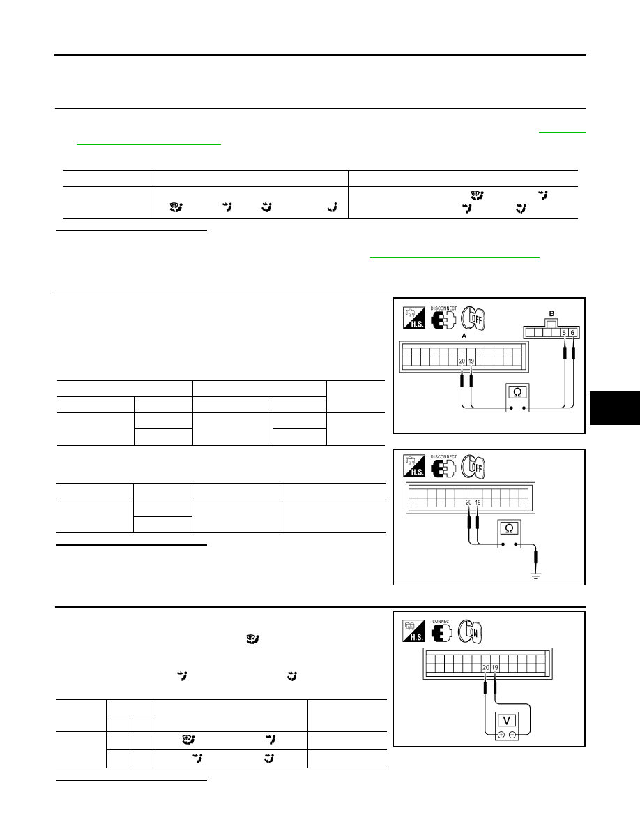
1. Turn ignition switch OFF.
2. Disconnect the front air control harness connector M180 (A) and
the mode door motor harness connector M142 (B).
3. Check continuity between front air control harness connector
M180 (A) terminals 19, 20 and the mode door motor harness
connector M142 (B) terminals 5, 6.
4. Check continuity between front air control harness connector
M180 terminals 19, 20 and ground.
Is the inspection result normal?
YES
>> GO TO 3.
NO
>> Repair or replace harness as necessary.
3.
CHECK FRONT AIR CONTROL FOR MODE DOOR MOTOR POWER AND GROUND
1. Reconnect front air control harness connector.
2. Turn ignition switch ON.
3. Press the mode switch to the D/F (
) mode.
4. Check voltage between front air control harness connector
M180 terminal 19 and terminal 20 while pressing the mode
switch to the VENT (
), and then the B/L (
) mode.
Is the inspection result normal?
YES
>> GO TO 4.
Monitor Item
Condition
Results
MODE FDBCK
Cycle mode switch through all modes, D/F
(
), VENT (
), B/L (
), and FOOT(
)
Voltage varies between D/F (
) and VENT (
), and
between VENT (
) and B/L (
).
A
B
Continuity
Connector
Terminal
Connector
Terminal
M180
19
M142
5
Yes
20
6
Connector
Terminal
—
Continuity
M180
19
Ground
No
20
AWIIA0364ZZ
AWIIA0361ZZ
Connector
Terminals
Condition Voltage
(Approx.)
(+) (-)
M180
19
20
D/F (
) mode to VENT (
) mode
Battery voltage
20
19
VENT (
) mode to B/L (
) mode
Battery voltage
AWIIA0360ZZ