Nissan Titan. Manual - part 379


  Index      Nissan     Nissan Titan (2014 year) - Service and Repair Manual


Search            


Content   ..  377  378  379  380   ..


Nissan Titan. Manual - part 379


SELF-DIAGNOSIS FUNCTION

HAC-21

< SYSTEM DESCRIPTION >

[AUTOMATIC AIR CONDITIONER]

C

D

E

F

G

H

J

K

L

M

A

B

HAC

N

O

P

SELF-DIAGNOSIS FUNCTION

Front Air Control Self-Diagnosis

INFOID:0000000009882446

A/C SYSTEM SELF-DIAGNOSIS FUNCTION

The self-diagnosis function is built into the front air control to quickly locate the cause of malfunctions.

DESCRIPTION

The self-diagnostic system diagnoses sensors, CAN system, and battery voltage on front air control Refer to

applicable sections (items) for details. Fault codes (if any are present) will be displayed in the ambient temper-

ature display area. Refer to 

HAC-21, "Front Air Control Self-Diagnosis Code Chart"

.

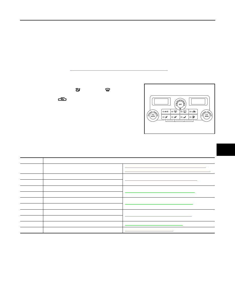
SELF-DIAGNOSTIC MODE

1. Press the OFF switch. 
2. Press the FLOOR/DEF (

) and DEF (

) mode switches

together and release on the front air control. 

3. Press the REC (

) to enter self diagnostic mode.

4. Turn ignition switch OFF to exit out of self-diagnostic mode.

Front Air Control Self-Diagnosis Code Chart

INFOID:0000000009882447

SELF-DIAGNOSTIC CODE CHART

AWIIA0938ZZ

Code No.

Reference page

03

Battery voltage out of range

CHG-4, "Work Flow (With EXP-800 NI or GR8-1200 NI)"

 or 

CHG-7, "Work Flow (Without EXP-800 NI or GR8-1200 NI)"

30

In-vehicle sensor circuit out of range (low)

HAC-59, "In-Vehicle Sensor Diagnosis Procedure"

31

In-vehicle sensor circuit out of range (high)

40

Ambient sensor circuit short

HAC-56, "Ambient Sensor Diagnosis Procedure"

41

Ambient sensor circuit open

50

Optical sensor (Driver) circuit open or short

HAC-62, "Optical Sensor Diagnosis Procedure"

52

Optical sensor (Passenger) circuit open or short

56

Intake sensor circuit short

HAC-64, "Intake Sensor Diagnosis Procedure"

57

Intake sensor circuit open

80

CAN bus fault

LAN-14, "Trouble Diagnosis Flow Chart"

90

Stuck button

VTL-8, "Removal and Installation"

HAC-22

< DTC/CIRCUIT DIAGNOSIS >

[AUTOMATIC AIR CONDITIONER]

MODE DOOR MOTOR

DTC/CIRCUIT DIAGNOSIS

MODE DOOR MOTOR

System Description

INFOID:0000000009882448

SYSTEM DESCRIPTION

Component Parts

Mode door control system components are:

• Front air control

• Mode door motor

• PBR (built into mode door motor)

• In-vehicle sensor

• Ambient sensor

• Optical sensor

• Intake sensor

System Operation

The mode door position (vent, B/L, foot, D/F, and defrost) is set by the front air control by means of the mode

door motor. When a mode door position is selected on the front air control, voltage is applied to one circuit of

the mode door motor while ground is applied to the other circuit, causing the mode door motor to rotate. The

direction of rotation is determined by which circuit has voltage applied to it, and which one has ground applied

to it. The front air control monitors the mode door position by measuring the voltage signal on the PBR circuit.

In AUTO mode the mode door position is set by the front air control which determines the proper position

based on inputs from the in-vehicle sensor, ambient sensor, optical sensor, intake sensor, and the temperature

selected by the driver or passenger.

Mode Door Control Specification

COMPONENT DESCRIPTION

Mode Door Motor 

WJIA1240E

WJIA0434E

MODE DOOR MOTOR

HAC-23

< DTC/CIRCUIT DIAGNOSIS >

[AUTOMATIC AIR CONDITIONER]

C

D

E

F

G

H

J

K

L

M

A

B

HAC

N

O

P

The mode door motor is attached to the heater & cooling unit assem-

bly. It rotates so that air is discharged from the outlet as indicated by

the front air control. Motor rotation is conveyed to a link which acti-

vates the mode door.

Mode Door Motor Component Function Check

INFOID:0000000009882449

INSPECTION FLOW

1.

CONFIRM SYMPTOM BY PERFORMING OPERATIONAL CHECK - DISCHARGE AIR

1. Press each mode switch and press the 

 (DEF) switch. Each position indicator should illuminate.

2. Confirm that discharge air comes out according to the air distribution table. Refer to 

HAC-15, "Discharge

Air Flow"

.

NOTE:

Confirm that the compressor clutch is engaged (visual inspection) and intake door position is at FRESH

 when DEF (

) or D/F (

) is selected.

Is the inspection result normal?

YES

>> Inspection End.

NO

>> Go to diagnosis procedure. Refer to 

HAC-23, "Mode Door Motor Diagnosis Procedure"

.

Mode Door Motor Diagnosis Procedure

INFOID:0000000009882450

Regarding Wiring Diagram information, refer to 

HAC-71, "Wiring Diagram - Automatic Air Conditioner"

.

SYMPTOM:

• Air outlet does not change.

• Mode door motor does not operate normally.

1.

CHECK MODE DOOR MOTOR POSITION BALANCED RESISTOR (PBR) FEEDBACK VOLTAGE

1. Turn ignition switch ON.

2. Using CONSULT, check "MODE FDBCK" in "DATA MONITOR" mode in "HVAC". Refer to 

HAC-17, "CON-

SULT Function (HVAC)"

.

3. Observe "MODE FDBCK" voltage while cycling front air control mode switch through all modes.

Is the inspection result normal?

YES

>> • Mode door motor is OK.

• Inspect mode door for mechanical failure. Refer to 

VTL-19, "Removal and Installation"

.

NO

>> GO TO 2.

2.

CHECK MODE DOOR MOTOR CIRCUITS FOR OPEN AND SHORT TO GROUND 

WJIA0587E

Monitor Item

Condition

Results

MODE FDBCK

Cycle mode switch through all modes, D/F 

(

), VENT (

), B/L (

), and FOOT(

)

Voltage varies between D/F (

) and VENT (

), and 

between VENT (

) and B/L (

).

HAC-24

< DTC/CIRCUIT DIAGNOSIS >

[AUTOMATIC AIR CONDITIONER]

MODE DOOR MOTOR

1. Turn ignition switch OFF.

2. Disconnect the front air control harness connector M49 (A) and

the mode door motor harness connector M142 (B).

3. Check continuity between front air control harness connector

M49 (A) terminals 19, 20 and the mode door motor harness con-

nector M142 (B) terminals 5, 6.

4. Check continuity between front air control harness connector

M49 terminals 19, 20 and ground.

Is the inspection result normal?

YES

>> GO TO 3.

NO

>> Repair or replace harness as necessary.

3.

CHECK FRONT AIR CONTROL FOR MODE DOOR MOTOR POWER AND GROUND 

1. Reconnect front air control harness connector.

2. Turn ignition switch ON.
3. Press the mode switch to the D/F (

) mode. 

4. Check voltage between front air control harness connector M49

terminal 19 and terminal 20 while pressing the mode switch to
the VENT (

), and then the B/L (

) mode. 

Is the inspection result normal?

YES

>> GO TO 4.

NO

>> Replace front air control. Refer to 

VTL-8, "Removal and Installation"

.

4.

CHECK MODE DOOR MOTOR PBR CIRCUITS FOR OPEN AND SHORT TO GROUND 

1. Turn ignition switch OFF.

2. Disconnect the front air control harness connectors.

3. Check continuity between front air control harness connector

M49 (C) terminal 3, and M50 (A) terminal 28 and the mode door

motor harness connector M142 (B) terminals 1, 3.

4. Check continuity between front air control harness connector

M49 (C) terminal 3, M50 (A) terminal 28 and ground.

A

B

Continuity

Connector

Terminal

Connector

Terminal

M49

19

M142

5

Yes

20

6

Connector

Terminal

Continuity

M49

19

Ground

No

20

AWIIA0364ZZ

AWIIA0361ZZ

Connector

Terminals

Condition Voltage 

(Approx.)

(+) (-)

M49

19

20

D/F (

) mode to VENT (

) mode

Battery voltage

20

19

VENT (

) mode to B/L (

) mode

Battery voltage

AWIIA0360ZZ

A and C

B

Continuity

Connector

Terminal

Connector

Terminal

M49 (C)

3

M142

3

Yes

M50 (A)

28

1

AWIIA0368ZZ


Content   ..  377  378  379  380   ..