Nissan Titan. Manual - part 364


  Index      Nissan     Nissan Titan (2014 year) - Service and Repair Manual


Search            


Content   ..  362  363  364  365   ..


Nissan Titan. Manual - part 364


PRECAUTIONS

HA-7

< PRECAUTION >

C

D

E

F

G

H

J

K

L

M

A

B

HA

N

O

P

CAUTION:

The new and former refrigerant connections use different O-ring configurations. Do not confuse O-

rings since they are not interchangeable. If a wrong O-ring is installed, refrigerant will leak at or

around the connection.

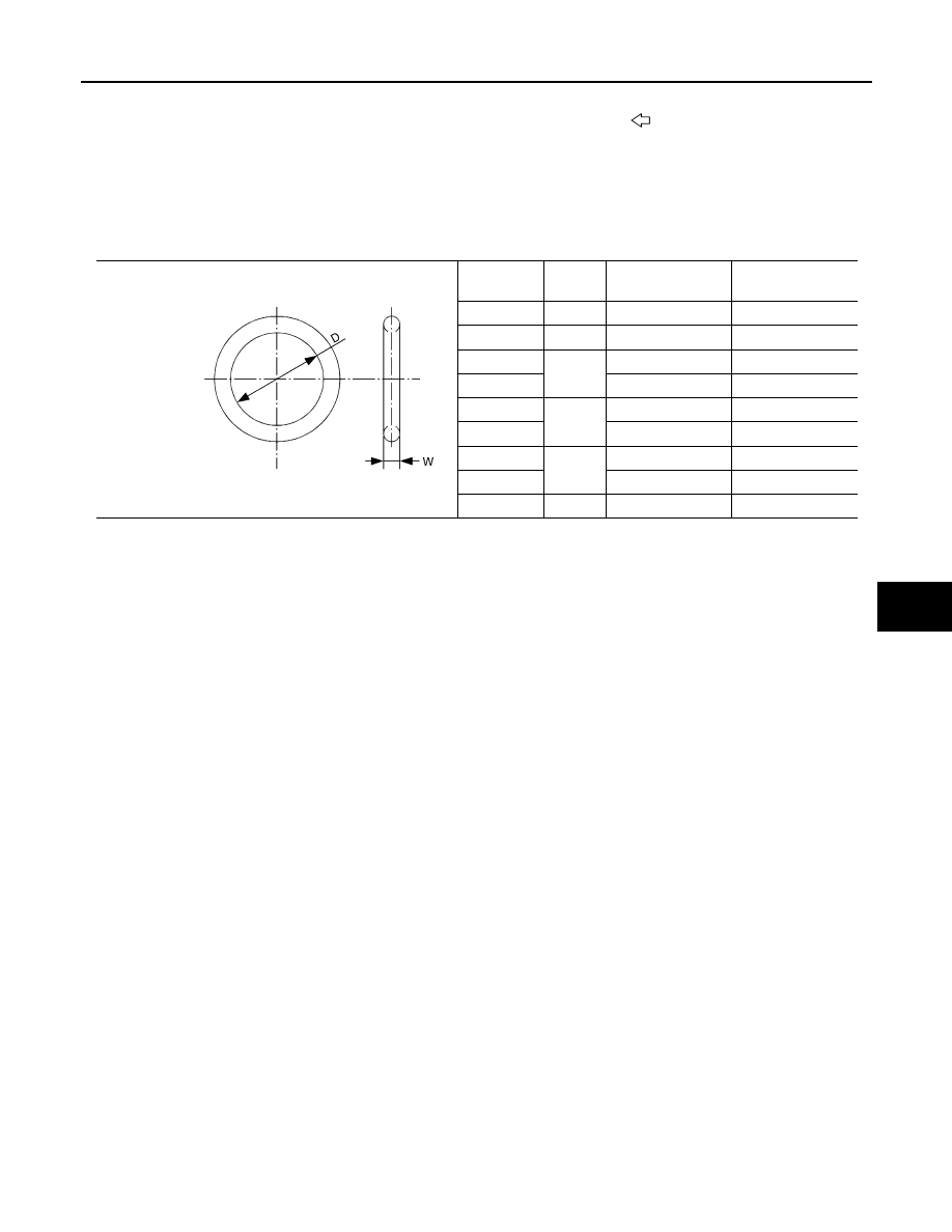
O-Ring Part Specifications*

*: Always check with the Parts Department for the latest parts information.

WARNING:

Make sure all refrigerant is discharged into the recycling equipment and the pressure in the system is

less than atmospheric pressure. Then gradually loosen the discharge side hose fitting and remove it.

CAUTION:

When replacing or cleaning refrigerant cycle components, observe the following.

• When the compressor is removed, store it in the same position as it is when mounted on the car.

Failure to do so will cause oil to enter the low pressure chamber.

• When connecting tubes, always use a torque wrench and a back-up wrench.

• After disconnecting tubes, immediately plug all openings to prevent entry of dirt and moisture.

• When installing an air conditioner in the vehicle, connect the pipes as the final stage of the opera-

tion. Do not remove the seal caps of pipes and other components until just before required for con-

nection.

• Allow components stored in cool areas to warm to working area temperature before removing seal

caps. This prevents condensation from forming inside A/C components.

• Thoroughly remove moisture from the refrigeration system before charging the refrigerant.

• Always replace used O-rings.

• When connecting tube, apply oil to circle of the O-rings shown in illustration. Be careful not to apply

oil to threaded portion.

Oil name: NISSAN A/C System Oil Type S or equivalent

• O-ring must be closely attached to dented portion of tube.

• When replacing the O-ring, be careful not to damage O-ring and tube.

• Connect tube until you hear it click, then tighten the nut or bolt by hand until snug. Make sure that

the O-ring is installed to tube correctly.

• After connecting line, conduct leak test and make sure that there is no leakage from connections.

When the gas leaking point is found, disconnect that line and replace the O-ring. Then tighten con-

nections of seal seat to the specified torque.

16.

Low-pressure flexible hose

17.

High-pressure flexible hose

18. Low-pressure service valve

19.

Low-pressure pipe

20.

Drain hose

Front

Connection 

type

O-ring 

size

D mm (in)

W mm (in)

New

8

6.8 (0.268)

1.85 (0.0728)

Former

10

9.25 (0.3642)

1.78 (0.0701)

New

12

10.9 (0.429)

2.43 (0.0957)

Former

11.0 (0.433)

2.4 (0.094)

New

16

13.6 (0.535)

2.43 (0.0957)

Former

14.3 (0.563)

2.3 (0.091)

New

19

16.5 (0.650)

2.43 (0.0957)

Former

17.12 (0.6740)

1.78 (0.0701)

New

24

21.8 (0.858)

2.4 (0.094)

SHA814E

HA-8

< PRECAUTION >

PRECAUTIONS

Precaution for Service of Compressor

INFOID:0000000009882403

• Plug all openings to prevent moisture and foreign matter from entering.

• When the compressor is removed, store it in the same position as it is when mounted on the car.

• When replacing or repairing compressor, follow “Maintenance of Oil Quantity in Compressor”

exactly. Refer to 

HA-22, "Maintenance of Oil Quantity in Compressor"

.

• Keep friction surfaces between clutch and pulley clean. If the surface is contaminated with oil, wipe

it off by using a clean waste cloth moistened with thinner.

• After compressor service operation, turn the compressor shaft by hand more than 5 turns in both

directions. This will equally distribute oil inside the compressor. After the compressor is installed,

let the engine idle and operate the compressor for 1 hour.

• After replacing the compressor magnet clutch, apply voltage to the new one and check for normal

operation. Refer to 

HA-33, "Removal and Installation"

.

Precaution for Service Equipment

INFOID:0000000009882404

RECOVERY/RECYCLING EQUIPMENT

Follow the manufacturer's instructions for machine operation and machine maintenance. Never introduce any

refrigerant other than that specified into the machine.

ELECTRONIC LEAK DETECTOR

Follow the manufacturer's instructions for tester operation and tester maintenance.

VACUUM PUMP

1.

Plug

2.

O-ring

A.

Torque wrench

B.

Apply oil

C.

Do not apply oil to threads

D.

NG (no good)

E.

OK (okay)

F.

Inflated portion

WJIA1774E

PRECAUTIONS

HA-9

< PRECAUTION >

C

D

E

F

G

H

J

K

L

M

A

B

HA

N

O

P

The oil contained inside the vacuum pump is not compatible with the

specified oil for HFC-134a (R-134a) A/C systems. The vent side of

the vacuum pump is exposed to atmospheric pressure so the vac-

uum pump oil may migrate out of the pump into the service hose.

This is possible when the pump is switched off after evacuation (vac-

uuming) and hose is connected to it.

To prevent this migration, use a manual valve situated near the

hose-to-pump connection, as follows.

• Usually vacuum pumps have a manual isolator valve as part of the

pump. Close this valve to isolate the service hose from the pump.

• For pumps without an isolator, use a hose equipped with a manual

shut-off valve near the pump end. Close the valve to isolate the

hose from the pump.

• If the hose has an automatic shut off valve, disconnect the hose

from the pump: as long as the hose is connected, the valve is open

and lubricating oil may migrate.

Some one-way valves open when vacuum is applied and close

under a no vacuum condition. Such valves may restrict the pump's

ability to pull a deep vacuum and are not recommended.

MANIFOLD GAUGE SET

Be certain that the gauge face indicates HFC-134a (R-134a or

134a). Make sure the gauge set has 1/2

″-16 ACME threaded con-

nections for service hoses. Confirm the set has been used only with

refrigerant HFC-134a (R-134a) along with specified oil.

SERVICE HOSES

Be certain that the service hoses display the markings described

(colored hose with black stripe). All hoses must include positive shut-

off devices (either manual or automatic) near the end of the hoses

opposite the manifold gauge.

SERVICE COUPLERS

RHA270D

SHA533D

RHA272D

HA-10

< PRECAUTION >

PRECAUTIONS

Do not attempt to connect HFC-134a (R-134a) service couplers to a

CFC-12 (R-12) A/C system. The HFC-134a (R-134a) couplers will

not properly connect to the CFC-12 (R-12) system. If an improper

connection is attempted, discharging and contamination may occur.

REFRIGERANT WEIGHT SCALE

Verify that no refrigerant other than HFC134a (R-134a) and specified

oils have been used with the scale. If the scale controls refrigerant

flow electronically, the hose fitting must be 1/2”-16 ACME.

CHARGING CYLINDER

Using a charging cylinder is not recommended. Refrigerant may be vented into air from cylinder's top valve

when filling the cylinder with refrigerant. Also, the accuracy of the cylinder is generally less than that of an

electronic scale or of quality recycle/recharge equipment.

Shut-off valve rotation

A/C service valve

Clockwise

Open

Counterclockwise

Close

RHA273D

RHA274D


Content   ..  362  363  364  365   ..