Nissan Titan. Manual - part 345


  Index      Nissan     Nissan Titan (2014 year) - Service and Repair Manual


Search            


Content   ..  343  344  345  346   ..


Nissan Titan. Manual - part 345


DRIVE SHAFT

FAX-13

< UNIT DISASSEMBLY AND ASSEMBLY >

C

E

F

G

H

I

J

K

L

M

A

B

FAX

N

O

P

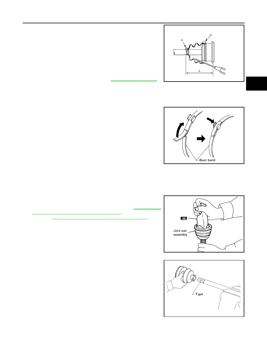
7. Install the boot securely into the grooves (indicated by * marks)

as shown.

CAUTION:

If there is grease on boot mounting surfaces (indicated by *

marks) of shaft and housing, boot may come off. Remove

all grease from surfaces.

8. Check that the boot installation length (L) is the length indicated

below. Insert a suitable tool into the large end of the boot, as

shown. Bleed air from the boot to prevent boot deformation.

CAUTION:

• The boot may break if the boot installation length is less than the specified value.

• Do not contact inside surface of boot with tip of the suitable tool.
9. Secure the large and small ends of the boot with the new boot

bands as shown. 

NOTE:

Discard the old boot bands and use new ones for assembly.

10. After installing the sliding joint housing to the drive shaft, rotate the boot to check that the boot is posi-

tioned correctly. If the boot is not positioned correctly, reposition the boot and secure the boot using a new

boot band.

Wheel Side

1. Insert the Genuine NISSAN Grease or equivalent, into the joint

sub-assembly serration hole until the grease begins to ooze

from the ball groove and serration hole. Refer to 

MA-15, "FOR

NORTH AMERICA : Fluids and Lubricants"

 (United States and

Canada), 

MA-16, "FOR MEXICO : Fluids and Lubricants"

 (Mex-

ico). After inserting the grease, use a shop cloth to wipe off the

grease that has oozed out.

2. Wrap the serrated part of the drive shaft with tape. Install the

boot band and boot onto the shaft. Do not damage the boot.

NOTE:

Discard the old boot band and boot and use a new one for

assembly.

3. Remove the protective tape wound around the serrated part of

the drive shaft.

Boot installation 

length (L) 

: Refer to 

FAX-15, "Drive Shaft"

.

WDIA0287E

SFA395

SDIA1127E

SFA800

FAX-14

< UNIT DISASSEMBLY AND ASSEMBLY >

DRIVE SHAFT

4. Attach the circlip to the drive shaft making sure circlip fits

securely into groove on drive shaft. Then install drive shaft nut to

end of joint sub-assembly, and press-fit the circlip using a suit-

able tool as shown.

NOTE:

Discard the old circlip and use a new one for assembly.

5. Insert the specified quantity of Genuine NISSAN Grease or

equivalent, into the joint sub-assembly and the large end of the

boot. Refer to 

MA-15, "FOR NORTH AMERICA : Fluids and

Lubricants"

 (United States and Canada), 

MA-16, "FOR MEXICO

: Fluids and Lubricants"

 (Mexico).

6. Install the boot securely into the grooves (indicated by the *

marks) as shown.

CAUTION:

If there is grease on the boot mounting surfaces (indicated

by the * marks) of the drive shaft and joint sub-assembly,

the boot may come off. Remove all grease from the drive

shaft surfaces. 

7. Check that the boot installation length (L) is the specified length.

Insert a suitable tool into the large end of the boot, as shown.

Bleed the air from the boot to prevent boot deformation. 

CAUTION:

• The boot may break if the boot installation length is less than the specified length.

• Do not contact inside surface of boot with the tip of the suitable tool.

8. Secure large and small ends of the boot using new boot bands

using tool as shown.

NOTE:

Discard the old boot bands and use new ones for assembly.

• Secure boot band so that dimension (M) meets specification

as shown.

9. After installing the housing to the shaft, rotate the boot to check that it is positioned correctly. If the boot is

not positioned correctly, remove the old boot bands then reposition the boot and secure the boot with new

boot bands.

Grease capacity : Refer to 

FAX-15, "Drive Shaft"

.

RAC0049D

Boot installation 

length (L)

: Refer to 

FAX-15, "Drive Shaft"

.

Tool number : KV40107300 ( — )

WDIA0288E

RAC1133D

Dimension (M)

: Refer to 

FAX-15, "Boot Bands"

.

DSF0047D

SERVICE DATA AND SPECIFICATIONS (SDS)

FAX-15

< SERVICE DATA AND SPECIFICATIONS (SDS) 

C

E

F

G

H

I

J

K

L

M

A

B

FAX

N

O

P

SERVICE DATA AND SPECIFICATIONS (SDS)

SERVICE DATA AND SPECIFICATIONS (SDS)

Wheel Bearing

INFOID:0000000009886177

Drive Shaft

INFOID:0000000009886178

Boot Bands

INFOID:0000000009886179

Unit: mm (in)

Axial end play

0.05 mm (0.002 in) or less

Drive shaft joint type

Final drive side

Rzeppa

Wheel side

Rzeppa

Grease

Quality

NISSAN Genuine Grease or 

equivalent

Capacity

Final drive side

130 - 150 g (4.58 - 5.29 oz)

Wheel side

145 - 165 g (5.11 - 5.82 oz)

Boot length

Final drive side (L

)

145 mm (5.71 in)

Wheel side (L)

168.4 mm (6.63 in)

WDIA0055E

Dimension (M)

1.0 - 4.0 (0.039 - 0.157)

DSF0047D

FL-1

ENGINE

C

D

E

F

G

H

I

J

K

L

M

SECTION 

FL

A

FL

N

O

P

CONTENTS

FUEL SYSTEM

PRECAUTION ...............................................

2

PRECAUTIONS ...................................................

2

Precaution for Supplemental Restraint System 
(SRS) "AIR BAG" and "SEAT BELT PRE-TEN-
SIONER" .................................................................
..

2

FUEL SYSTEM ....................................................

3

General Precaution  ...................................................

3

PREPARATION ............................................

4

PREPARATION ...................................................

4

Special Service Tool  .................................................

4

Commercial Service Tool  ..........................................

4

BASIC INSPECTION  ....................................

5

FUEL SYSTEM ....................................................

5

Checking Fuel Line  ...................................................

5

UNIT REMOVAL AND INSTALLATION  .......

6

FUEL TANK .........................................................

6

Removal and Installation ...........................................

6

FUEL LEVEL SENSOR UNIT, FUEL FILTER 
AND FUEL PUMP ASSEMBLY  ........................

11

Removal and Installation  .........................................

11

EVAP CANISTER ..............................................

16

Exploded View .........................................................

16

Removal and Installation  .........................................

16

Component Inspection .............................................

17

UNIT DISASSEMBLY AND ASSEMBLY  ....

18

FUEL LEVEL SENSOR UNIT, FUEL FILTER 
AND FUEL PUMP ASSEMBLY  ........................

18

Exploded View .........................................................

18

Disassembly and Assembly .....................................

18

SERVICE DATA AND SPECIFICATIONS 
(SDS) ............................................................

19

SERVICE DATA AND SPECIFICATIONS 
(SDS) .................................................................

19

Standard and Limit  ..................................................

19


Content   ..  343  344  345  346   ..